Jaw members and methods of manufacture

a technology of jaw members and jaws, applied in the field of surgical instruments, can solve the problems of complex and costly machining operations

Inactive Publication Date: 2016-09-08
TYCO HEALTHCARE GRP LP
View PDF9 Cites 734 Cited by
  • Summary
  • Abstract
  • Description
  • Claims
  • Application Information

AI Technical Summary

Problems solved by technology

These machining operations can be complex and costly.

Method used


Image

  • Jaw members and methods of manufacture
  • Jaw members and methods of manufacture
  • Jaw members and methods of manufacture

Examples


Embodiment Construction

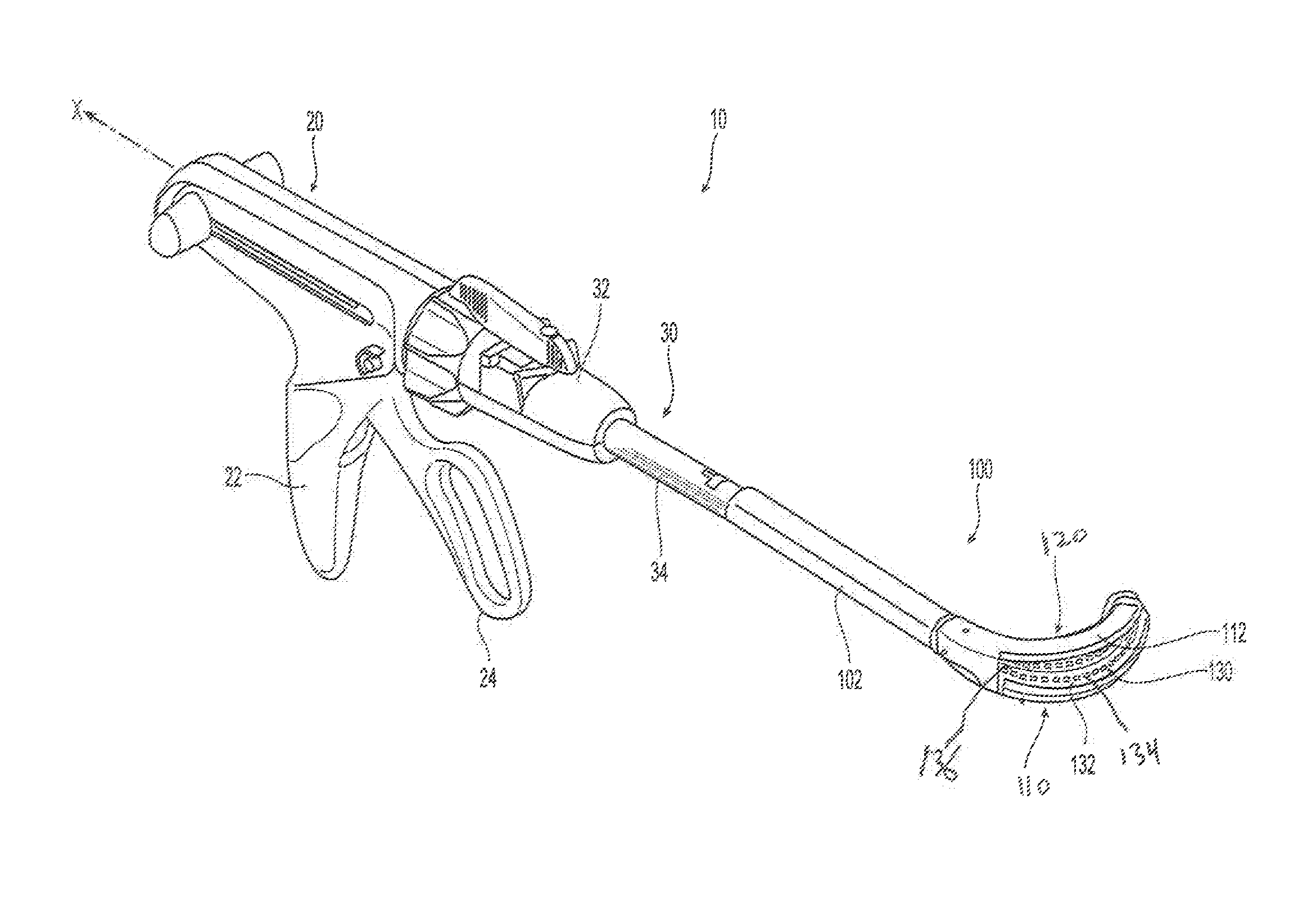
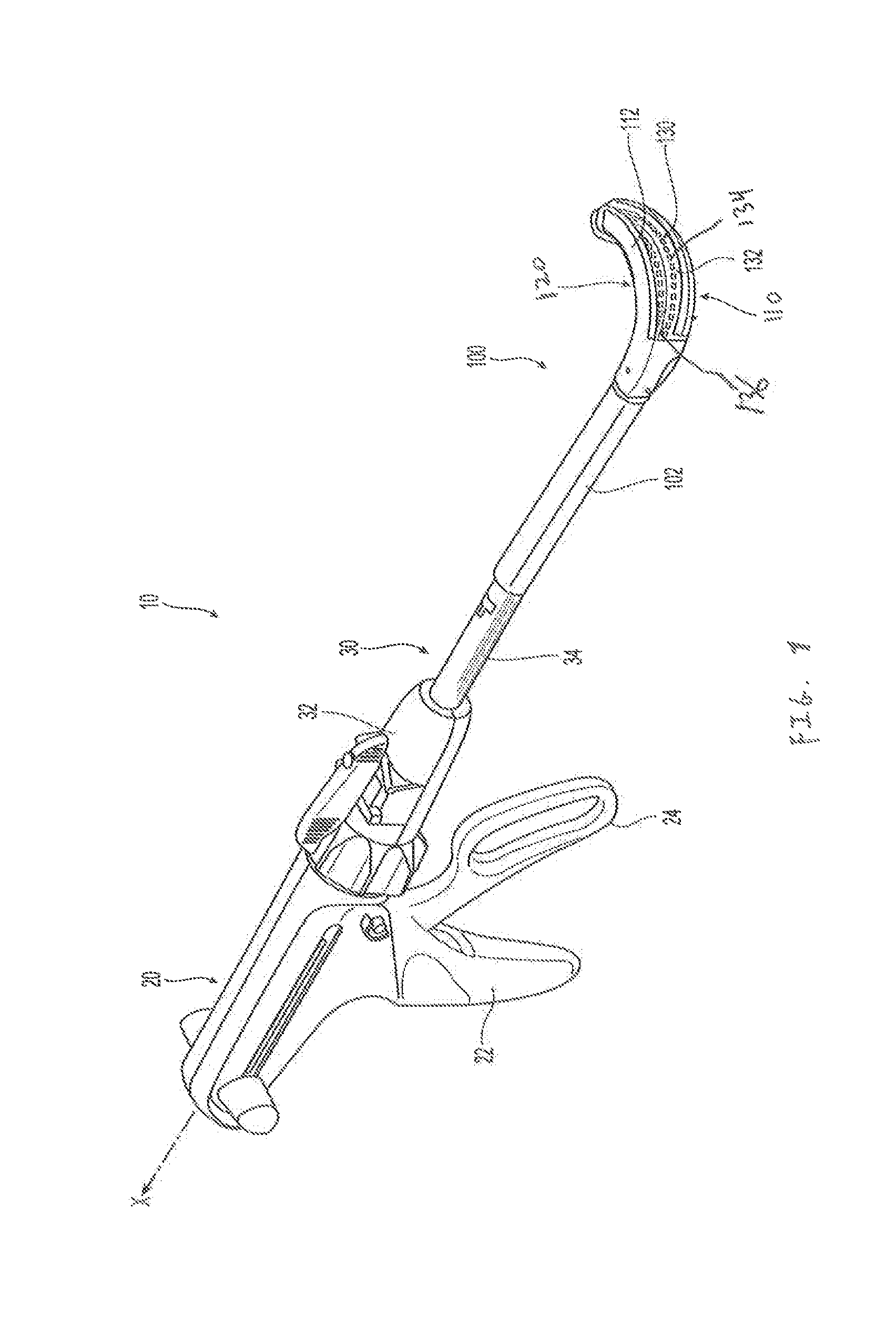
[0027]Embodiments of the presently disclosed surgical stapling instrument are described in detail with reference to the drawings, wherein like reference numerals designate similar or identical elements in each of the several views. In the drawings and the description that follows, the term “proximal” refers to the end of the surgical stapling instrument, or component thereof, that is closest to the operator, whereas the term “distal” refers to the end of the surgical stapling instrument, or component thereof, that is farthest from the operator. As appreciated by one skilled in the art, the depicted surgical stapling instrument fires staples, but it may be adapted to fire any other suitable fastener such as clips and two-part fasteners.

[0028]As used herein, the terms parallel and perpendicular are understood to include relative configurations that are substantially parallel and substantially perpendicular up to about + / −10 degrees from true parallel and true perpendicular.
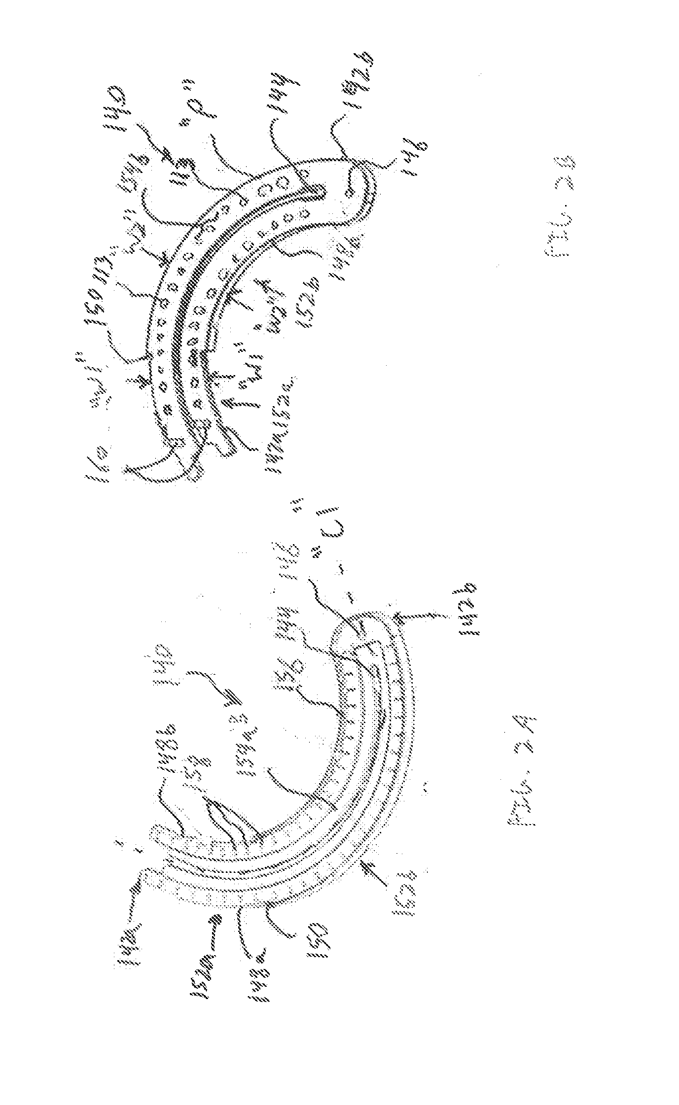
[0029]With ...


PUM

PropertyMeasurementUnit
thermoplasticaaaaaaaaaa
surface featureaaaaaaaaaa
lengthaaaaaaaaaa

Abstract

An anvil assembly for use with a surgical stapling instrument includes an anvil plate and an anvil cover each being fabricated from a thermoplastic material. The anvil plate includes a first surface and a second surface opposite the first surface. The first surface has a plurality of beads disposed along a periphery thereof. The anvil cover is configured to be coupled to a distal end of the surgical stapling instrument. The anvil cover includes a surface having at least one elongate surface feature disposed along a periphery thereof. The beads of the anvil plate and the elongate surface feature of the anvil cover are configured for abutting engagement upon assembly thereof.

Description

BACKGROUND[0001]1. Technical Field[0002]The present disclosure relates generally to surgical instruments and, more specifically, to surgical instruments for surgically joining tissue and methods of manufacturing / assembling jaw members of surgical instruments.[0003]2. Background of Related Art[0004]Surgical stapling instruments used for applying parallel rows of staples through compressed living tissue are well known in the art. These surgical instruments are commonly employed for closing tissue or organs prior to transaction or resection, for occluding organs in thoracic and abdominal procedures, and for fastening tissue in anastomoses.[0005]Typically, such surgical stapling instruments include an anvil assembly, a cartridge assembly for supporting an array of surgical staples, an approximation mechanism for approximating the anvil and cartridge assemblies, and a firing mechanism for ejecting the surgical staples from the cartridge assembly.[0006]In use, a surgeon initially approxim...

Claims


Application Information

Patent Timeline
Patent Type & Authority Applications(United States)
IPC IPC(8): A61B17/072B29C65/78B29C65/08
CPCA61B17/072B29C65/08B29C65/7802B29K2071/00A61B2017/07257B29L2031/7546A61B2017/07221A61B2017/07278A61B17/07207A61B2017/00526A61B17/29A61B2017/00955A61B2017/00964A61B2017/2945
Inventor PINJALA, VENKATA RAMANA MOHANNUKALA, RAJASEKHAR
Owner TYCO HEALTHCARE GRP LP
Why Eureka
Try Eureka