Footwear with tapered heel, support plate, and impact point measurement methods therefore

a technology of support plate and foot, applied in the field of footwear, can solve the problems of insufficient product availability, insufficient utilization of inability to fully utilize plantar and ankle mechanisms,

Active Publication Date: 2016-09-29
STIEN KARL
View PDF4 Cites 18 Cited by
  • Summary
  • Abstract
  • Description
  • Claims
  • Application Information

AI Technical Summary

Benefits of technology

[0007]Applicant has recognized the footwear industry today tends to lack knowledge of how the foot biomechanically conforms to surfaces or performs when hiking, running, or walking, or recognizes that the industry simply provides products inadequate in this regard. The midfoot or forefoot are designed or have evolved in such a way that when a foot comes in contact with a surface, flexion of the ankle and plantar mechanism occur and the impact is placed upon the muscle fibers in such a way that provides for efficient relaxation-contraction and allows a powerful stride. Applicant has recognized that when the impact from contacting a surface is placed within the heel area, the plantar and ankle mechanisms are not utilized, or are not optimally utilized. The biomechanical structure of a heel impact forces the knee and hip to absorb the force, or absorb a greater-than-natural force, causing injury. Shoes today are cushioned in the heel and provide only minimal mitigation of the forces absorbed by the body during a heel strike. Without heel cushioning, and over longer distances, the heel impacts will result in painful sensory feedback, and to avoid the discomfort, a person will naturally shift the impact from the heel to the mid to fore-foot. Such heel cushioning over time can cause dramatic injury, particularly with heavier individuals and those who travel far distances. The current footwear with a cushioned heel absorbs enough of the heel impact to bypass the heel's sensory feedback. Over time and distance, the lack of sensory feedback with a cushioned heel impact often result in chronic injury to the plantar mechanism, knees, hips and / or spine.
[0008]Applicant has developed a sole believed to minimize strain upon the knees, hips, and spine, and decrease injury and allow natural foot / ankle movement. Biomechanically, an individual's foot is built to walk without shoes. Therefore, the arch and plantar mechanism are designed to act as a spring when the forefoot is loaded on impact. The thicker tissue on the foot demonstrates where a foot should truly contact a surface. The thick tissue padding extends from the posterior part of a foot, down through the lateral side of the foot, across the lateral metatarsals and ends in the forefront of the foot. There is also thicker tissue at the end of each toe. Applicant recognizes the arch region has no such tissue thickening. The heel pad is meant to support static standing for balance, but not meant to absorb the impact associated with a striding motion.
[0009]“Barefoot” shoes permit sensory feedback given by the heel, thus decreasing the individual's likelihood of making a heel strike. However the barefoot shoe lacks comfort when contacting the surface because it lacks significant thickness in cushioning at the impact zones of the lateral midfoot-foot and forefoot. Further unrecognized in existing footwear's technology today is the failure to address and promote the biomechanically correct method of running and walking. One aspect of Applicant's invention allows for a rigid plate-like heel which gradually tapers into an adequately cushioned pad at the lateral midfoot area. The plate-like material extends to or through the forefoot / metatarsals while the pad extends to or through to the toes. Applicant refers to the cushioned area at the midfoot area as the “impact zone.” In this midfoot area or impact zone is a junction where the tapered heel transitions to a flattened lateral portion at the midfoot. In one aspect a junction line is defined. Impact point or points lie along the junction line, also referred to as the impact line. The junction or junction line is positioned anterior the pivot point of the ankle of a wearer such that the ankle will dorsiflex (i.e., toes point upward), absorb the energy of the foot strike by loading the soleus / gastrocnemius, and then release that energy at the end of the stride. There is limited or no padding between the person's heel and the rigid plate. There is padding between the wearer's midfoot and the rigid plate, with such padding gradually increasing from the posterior aspect of the midfoot to the anterior aspect of the midfoot. The padding may increase because the plate slopes downward from an upper area of the sole to a lower area of the sole. In one example the rigid plate spans substantially or the entirety of the width of the heel and midfoot. In another example the rigid plate spans primarily along the medial aspect of the midfoot while avoiding the lateral aspect. In one aspect a pad or cushioned area lies laterally along the midfoot corresponding to where a foot's natural padding is positioned. In one example the rigid plate extends from the heel through the medial and central midfoot arch. In some aspects the plate has some inherent flex which may provide a springing action. A plate may be made from a variety of materials, including but not limited to carbon fiber.
[0010]The plate is configured to support the heel (which heel is suspended posteriorly due to the tapered orientation of the heel, i.e., absence of material positioned below the heel and above the surface) and prevent impact occurring between the arch of the foot and the surface. While the weight or force of the wearer acts upon the plate at the medial and central midfoot arch during a step or stride, the heel is supported / suspended by the rigid plate which extends posteriorly. The rigid plate operates as a spring or dampening force or anti-sag mechanism, storing energy during the early phase of the stride and then releasing it at or toward the end of the stride.

Problems solved by technology

Applicant has recognized the footwear industry today tends to lack knowledge of how the foot biomechanically conforms to surfaces or performs when hiking, running, or walking, or recognizes that the industry simply provides products inadequate in this regard.
Applicant has recognized that when the impact from contacting a surface is placed within the heel area, the plantar and ankle mechanisms are not utilized, or are not optimally utilized.
The biomechanical structure of a heel impact forces the knee and hip to absorb the force, or absorb a greater-than-natural force, causing injury.
Shoes today are cushioned in the heel and provide only minimal mitigation of the forces absorbed by the body during a heel strike.
Without heel cushioning, and over longer distances, the heel impacts will result in painful sensory feedback, and to avoid the discomfort, a person will naturally shift the impact from the heel to the mid to fore-foot.
Such heel cushioning over time can cause dramatic injury, particularly with heavier individuals and those who travel far distances.
Over time and distance, the lack of sensory feedback with a cushioned heel impact often result in chronic injury to the plantar mechanism, knees, hips and / or spine.
However the barefoot shoe lacks comfort when contacting the surface because it lacks significant thickness in cushioning at the impact zones of the lateral midfoot-foot and forefoot.
Further unrecognized in existing footwear's technology today is the failure to address and promote the biomechanically correct method of running and walking.

Method used


Image

  • Footwear with tapered heel, support plate, and impact point measurement methods therefore
  • Footwear with tapered heel, support plate, and impact point measurement methods therefore
  • Footwear with tapered heel, support plate, and impact point measurement methods therefore

Examples


Embodiment Construction

[0029]The subject inventive system may take on numerous physical and method embodiments within the spirit of the invention and only preferred embodiments have been described in detail below, which are not meant to limit the scope and / or spirit of the invention.

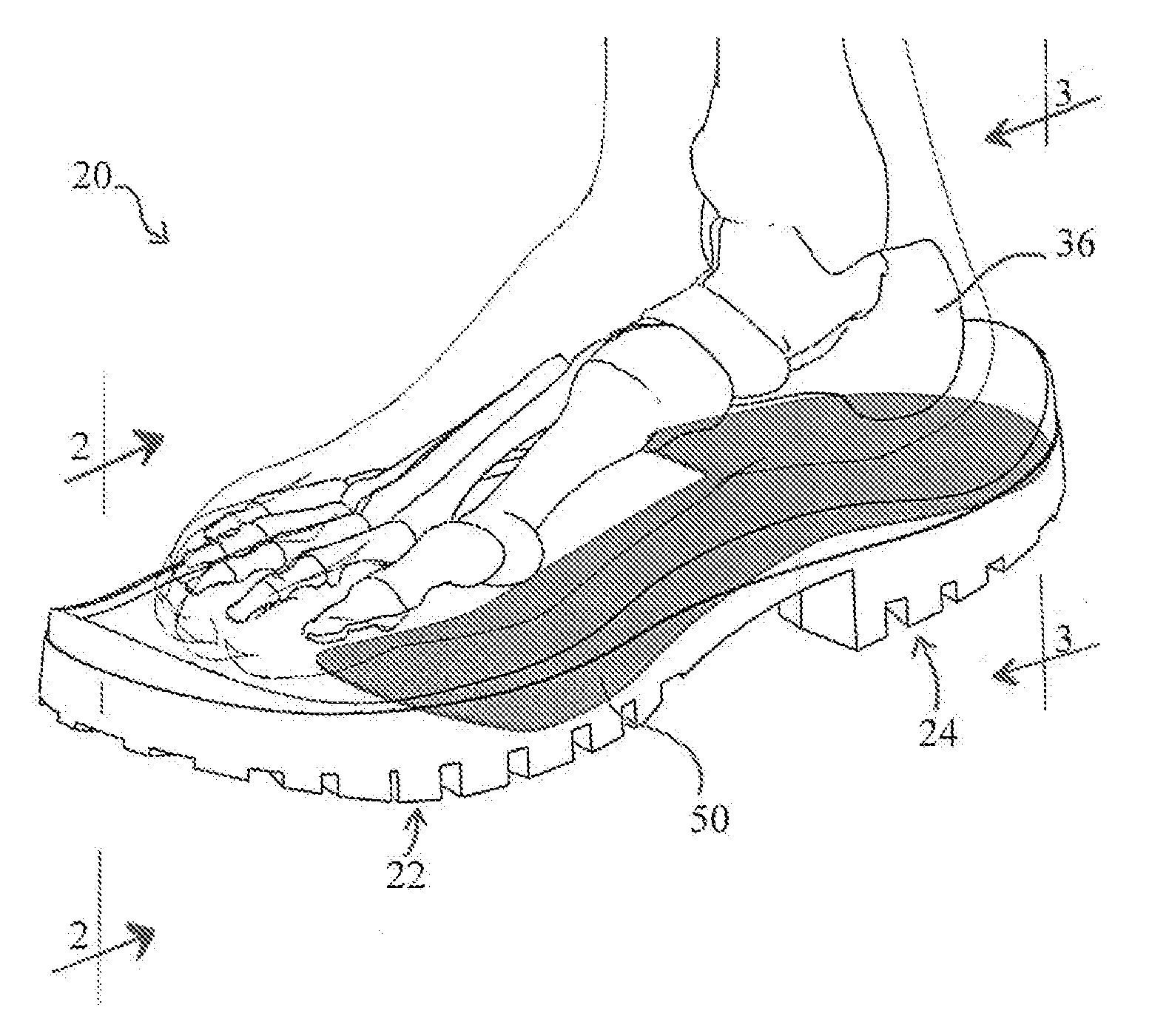
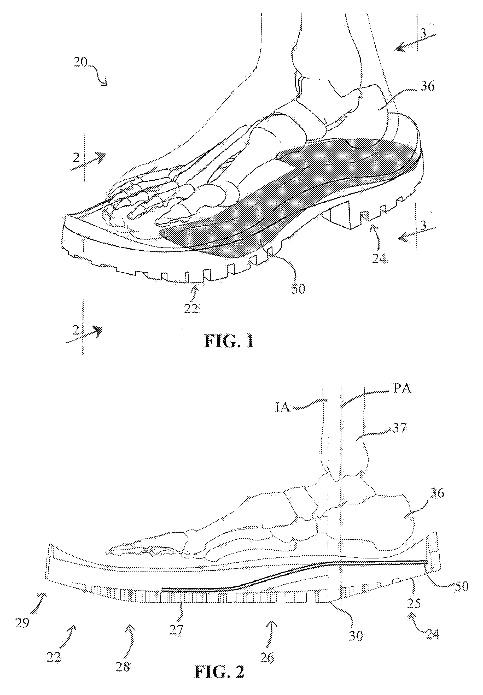
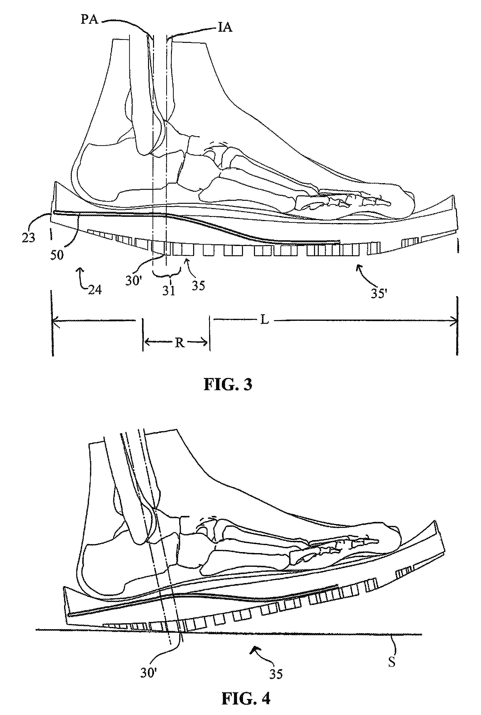
[0030]Human foot bones and structures have inspired the present invention. Aspects of the invention include a tapered / angled heel sole of an article of footwear and a combined heel support mechanism as further shown below.

[0031]Applicant appreciates that current footwear fails to address the need for true bio-mechanical movement throughout the foot. The need for a bio-mechanical design to allow proper impact of a foot to a surface is imperative to prevent injuries and fatigue, and to provide comfort for the consumer.

[0032]Applicant has come to appreciate that bio-mechanically the midfoot or forefoot are the appropriate sites for impact with running, hiking, or walking, which allows the arch of the foot and the plantar mechanis...


PUM


Abstract

An article of footwear having a tapered heel in part defining an impact point associated with a padded impact zone which first strikes a surface upon a foot plant and a plate embedded within a sole of the article such that the plate supports the heel of the sole from flexing or collapsing, the impact point positioned anterior a pivot point of the wearer's ankle. In one aspect the plate avoids positioning at a lateral midfoot area of the sole to allow for impact zone padding and promotes avoiding or reducing heel strike forces when walking or running.

Description

CROSS-REFERENCE TO RELATED APPLICATIONS[0001]The present application claims the benefit and priority of Provisional Patent Application Ser. No. 62 / 136,756, filed Mar. 23, 2015, FOR FOOTWEAR WITH TAPERED HEEL AND ARCH SPRINGS, under 35 U.S.C. §119(e), incorporated herein by reference as if fully reproduced herein.BACKGROUND OF THE INVENTION[0002]1. Field of the Invention[0003]The present inventive concept relates generally to footwear having a special sole to provide for improved bio-mechanical operation, including improved foot-plant and together with a support mechanism for enhanced comfort and use.[0004]2. Background Information[0005]There are numerous types and styles of footwear and soles for use with footwear. Some examples of footwear having various sole design and various springing mechanisms include those disclosed in patents such as U.S. Pat. No. 8,209,883, U.S. Patent No. 7,231,728, U. S. Pat. No. 8,474,154, U.S. Pat. No. 4,128,950, U.S. Patent Application No. 2013 / 0205619...

Claims


Application Information

Patent Timeline
Patent Type & Authority Applications(United States)
IPC IPC(8): A43B7/20A43B13/18
CPCA43B13/181A43B7/20A43B13/125A43B13/185A43B13/145A43B13/143A43B13/183A43B7/142A43B7/144A43B13/41A43B13/12
Inventor STIEN, KARL
Owner STIEN KARL
Why Eureka
Try Eureka