
Foldaway wall bed mounting

a technology for folding beds and support plates, applied in the direction of beds, couches, sofas, etc., can solve the problems of customers not following the installation directions correctly, the springs that collapse the bed inflicting serious injury or death, and the limitations of conventional foldaway beds, etc., to achieve the effect of increasing and decreasing the height of the pair of support plates

Inactive Publication Date: 2016-09-29
WILSON STEPHEN L
View PDF5 Cites 4 Cited by
  • Summary
  • Abstract
  • Description
  • Claims
  • Application Information

AI Technical Summary

Benefits of technology

The foldaway wall bed mounting is a device that allows a bed frame to be folded up against a wall. It consists of two support plates and a folding mechanism. The support plates are attached to the wall via a wall connector and the folding mechanism is attached to each support plate. The folding mechanism includes a spring assembly and a pivotable arm that connects to the bed frame. This allows the bed frame to move between a vertical folded position and a horizontal open position. An adjustable leg leveler can also be included to adjust the height of the support plates. The foldable wall bed mounting allows for easy movement and adjustability for different wall panel widths and thicknesses.

Problems solved by technology

However, conventional foldaway beds have certain serious limitations due to complicated construction, difficulty in folding or extending and more importantly have safety issues due to methods of mounting to a support wall.
There exists numerous instances where the top rail anchors or screws have pulled out of the wall studs causing the springs to collapse the bed inflicting serious injury or death.
Since, these beds are marketed as a do-it-yourself type product, customers may not follow the installation directions correctly.
In addition, the spring mechanism bears hundreds of pounds of pressure when the foldaway bed is operated, and the pressure is exerted on the nail rail attachment, which may cause the entire bed assembly to fall or pull away from the wall support.

Method used


Image

  • Foldaway wall bed mounting
  • Foldaway wall bed mounting
  • Foldaway wall bed mounting

Examples


Embodiment Construction

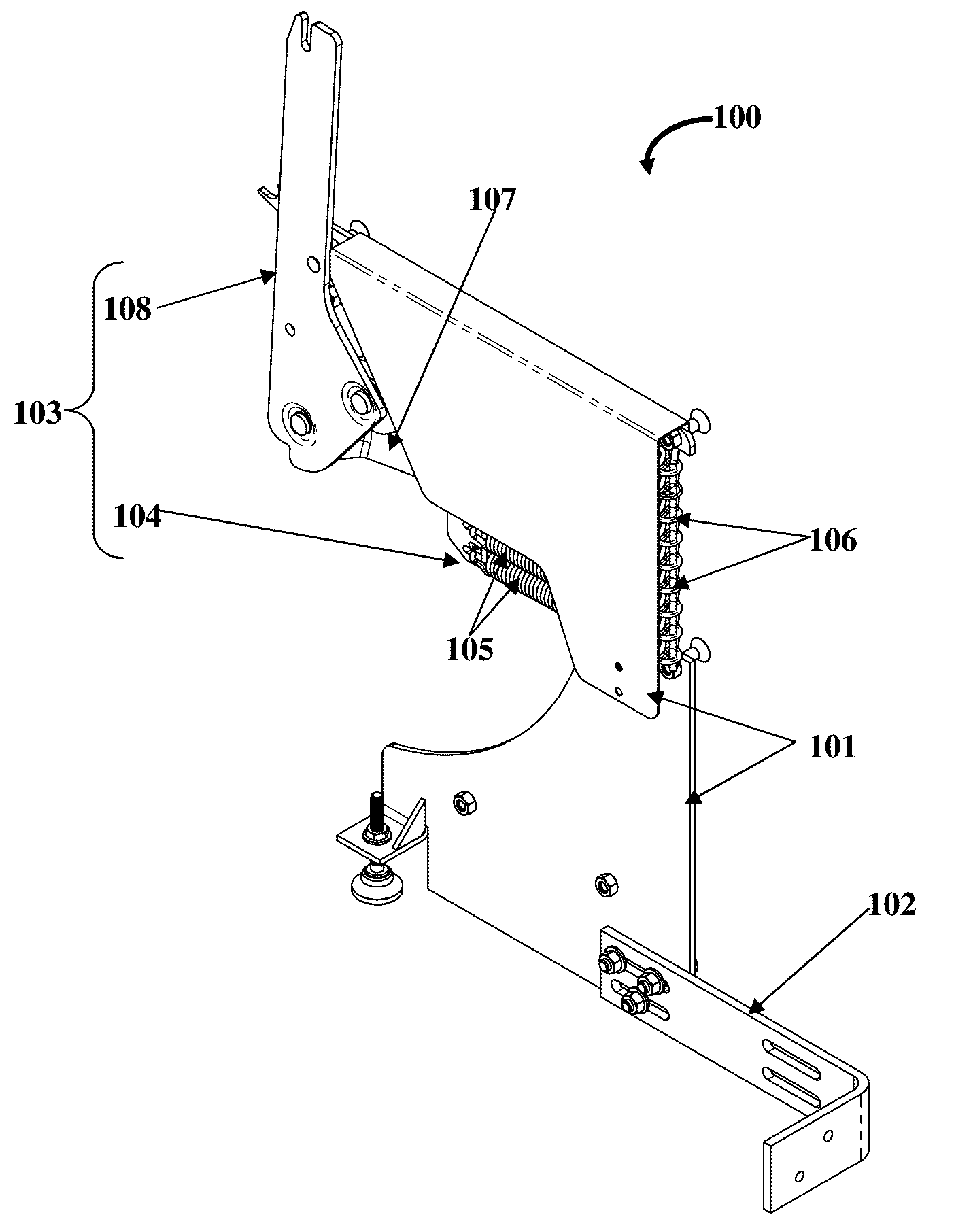
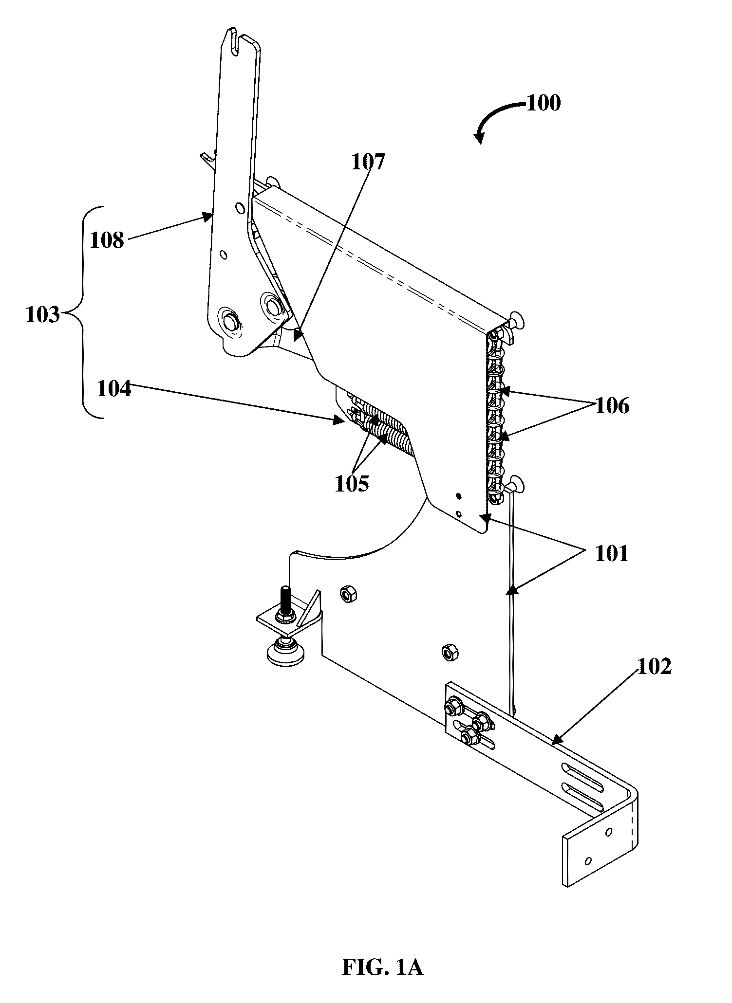
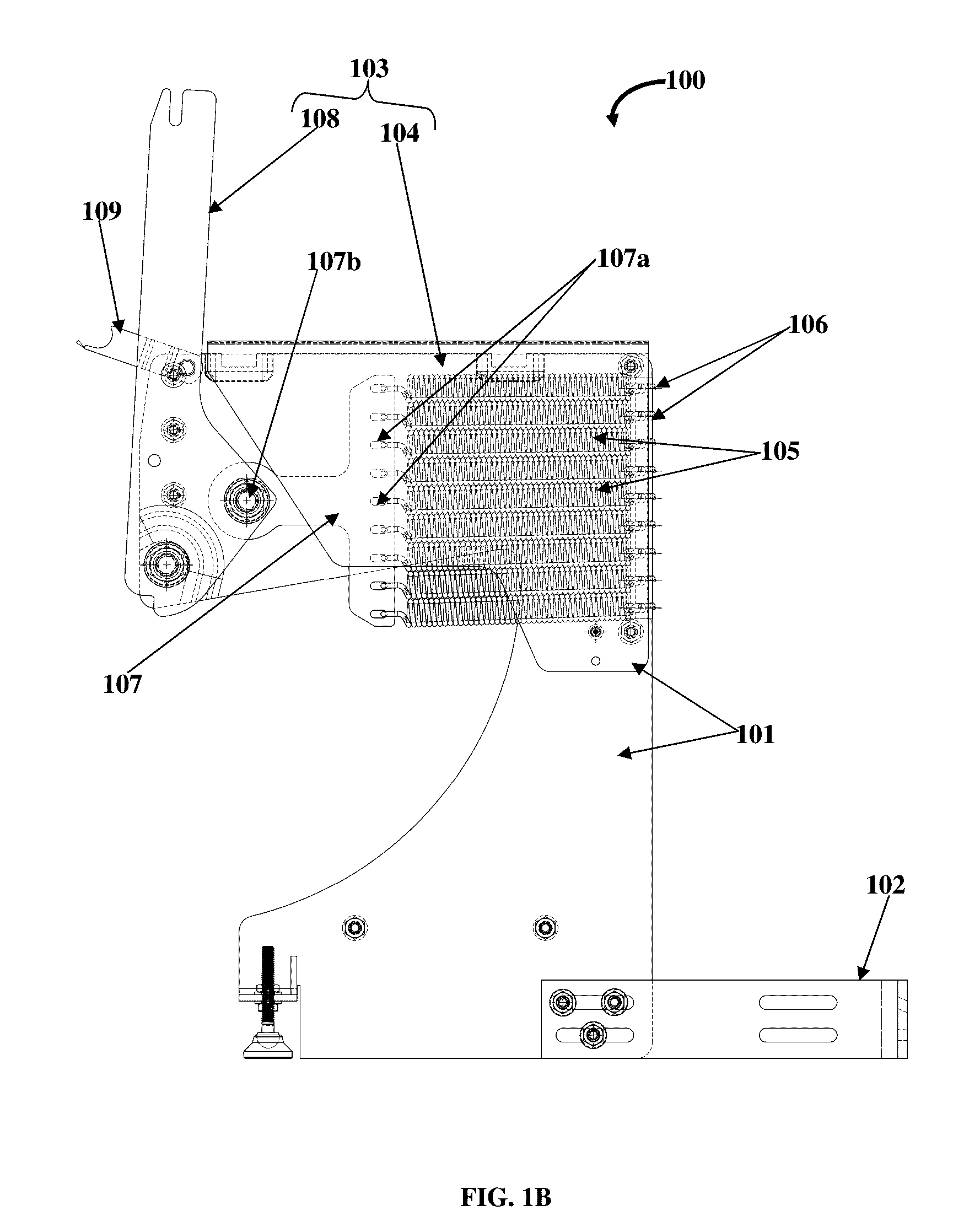
[0017]FIG. 1A is a perspective view of a left side foldaway wall bed mounting 100, FIG. 1B is a side view of the foldaway wall bed mounting 100, and FIG. 1C is a rear view of the foldaway wall bed mounting 100. The foldaway wall bed mounting 100 is configured to fold a bed frame 400 as shown in FIG. 4, to a wall, and the foldaway wall bed mounting 100 comprises a pair of support plates 101, and a folding mechanism 103. The pair of support plates 101 are spaced apart and mountable perpendicularly to the bottom of a solid wall support via a wall connector 102. The folding mechanism 103 is attachable to each of the support plates 101, the folding mechanism 103 comprises a spring assembly 104, and a pivotable arm 108. The spring assembly 104 comprises multiple spring members 105 fastened to a series of openings 106 defined on a side of the support plates 101, and the distal ends of the spring members 105 are fastened to openings 106 positioned on one end of a spring bracket 107. The piv...


PUM


Abstract

A foldaway wall bed mounting to fold a bed frame to a wall comprising support plates, and a folding mechanism. The support plates are spaced apart and mountable perpendicularly to the bottom of a solid wall support via a wall connector. The folding mechanism is attachable to each of the support plates comprises a spring assembly, and a pivotable arm. The spring assembly comprises spring members fastened to openings defined on a side of the support plates, and the distal ends of the spring members are fastened to openings on a spring bracket. The pivotable arm is hingedly connected to an opposing end of the spring bracket, and the pivotable arm is adapted to engage with a side rail of the bed frame, whereby the spring assembly provides controlled movement of pivotable arm which enables movement of the bed frame between a vertical folded position and a horizontal open position.

Description

CROSS-REFERENCE TO RELATED APPLICATION[0001]This application claims priority to the U.S. Provisional Patent application No. 62 / 136,723 filed in the United States Patent and Trademark Office on Mar. 23, 2015, entitled “FOLDABLE BED MOUNTING ASSEMBLY”. The specification of the above referenced patent application is incorporated herein by reference in it's entirelyBACKGROUND[0002]Foldaway beds, such as, wall beds or murphy beds and similar wall-enclosed pieces of furniture have been widely used where available space within a room is limited. Foldaway beds have become increasingly popular in recent years because of the limited space available in homes, wherein the bed can be extended from a folded position when needed to provide temporary sleeping accommodations and can be folded back against the wall when not in use. These type of beds are generally provided with a folding mechanism that allows the bed to pivot upwards from its horizontal usage position to a vertical storage position a...

Claims


Application Information

Patent Timeline
Patent Type & Authority Applications(United States)
IPC IPC(8): A47C17/40
CPCA47C17/40
Inventor WILSON, STEPHEN L.
Owner WILSON STEPHEN L
Learn More