
Displaced force backing wedge

a wedge and force technology, applied in the direction of nail extractors, lifting devices, manufacturing tools, etc., can solve the problems of extra work for users, inability to work well, and marring of the surrounding wall surface,

Inactive Publication Date: 2006-03-16
LAWSON JEFFREY G
View PDF5 Cites 1 Cited by
  • Summary
  • Abstract
  • Description
  • Claims
  • Application Information

AI Technical Summary

Benefits of technology

[0009] Another object of the invention is to provide a hand held wedge shaped protective device that can allow the user to increase or decrease the height of leverage needed when loosening a nail or trim board or the like.
[0010] Another object of the invention is to provide a hand held wedge shaped protective device that improves stabilization of a crow bar or hammer while in use for prying.
[0011] A further object of the invention is to provide a hand held wedge shaped protective device that is easy and convenient for the user to hold during use.

Problems solved by technology

Unfortunately, during the process, the surrounding wall surface such as sheet rock or relatively soft wood can become marred by the removal tool because the opposing force exerted by the underside of the removal tool is located in a relatively small area and can thereby cause dents or marring.
This causes extra work for the user because the dents or mars have to be filled and refinished.
Unfortunately, these items were not designed specifically for the intended use and therefore do not always work well.
For example, using a putty knife under a crow bar or hammer claw may be too thin and not give enough leverage for the extraction or loosening process.
When using a piece of wood, the user must find the proper thickness of wood, and there is always the danger of not spreading the force enough so that a dent or mar is still a possibility.
Additionally, a spatula or piece of wood is generally a flat surface and does not give lateral stability to the crow bar or claw hammer during use.

Method used


Image

  • Displaced force backing wedge
  • Displaced force backing wedge
  • Displaced force backing wedge

Examples


Embodiment Construction

[0020] Detailed descriptions of the preferred embodiment are provided herein. It is to be understood, however, that the present invention may be embodied in various forms. Therefore, specific details disclosed herein are not to be interpreted as limiting, but rather as a basis for the claims and as a representative basis for teaching one skilled in the art to employ the present invention in virtually any appropriately detailed system, structure or manner.

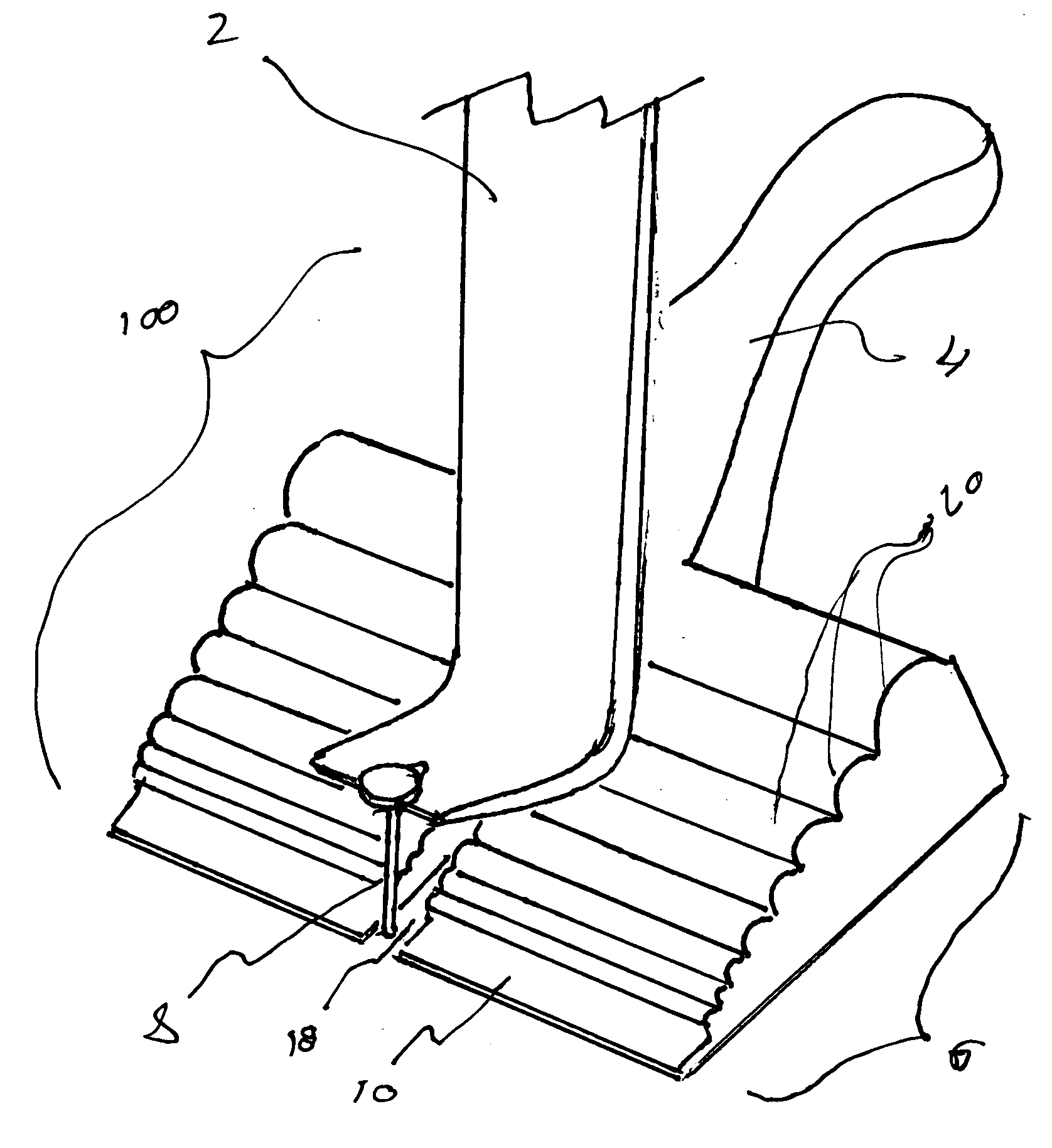
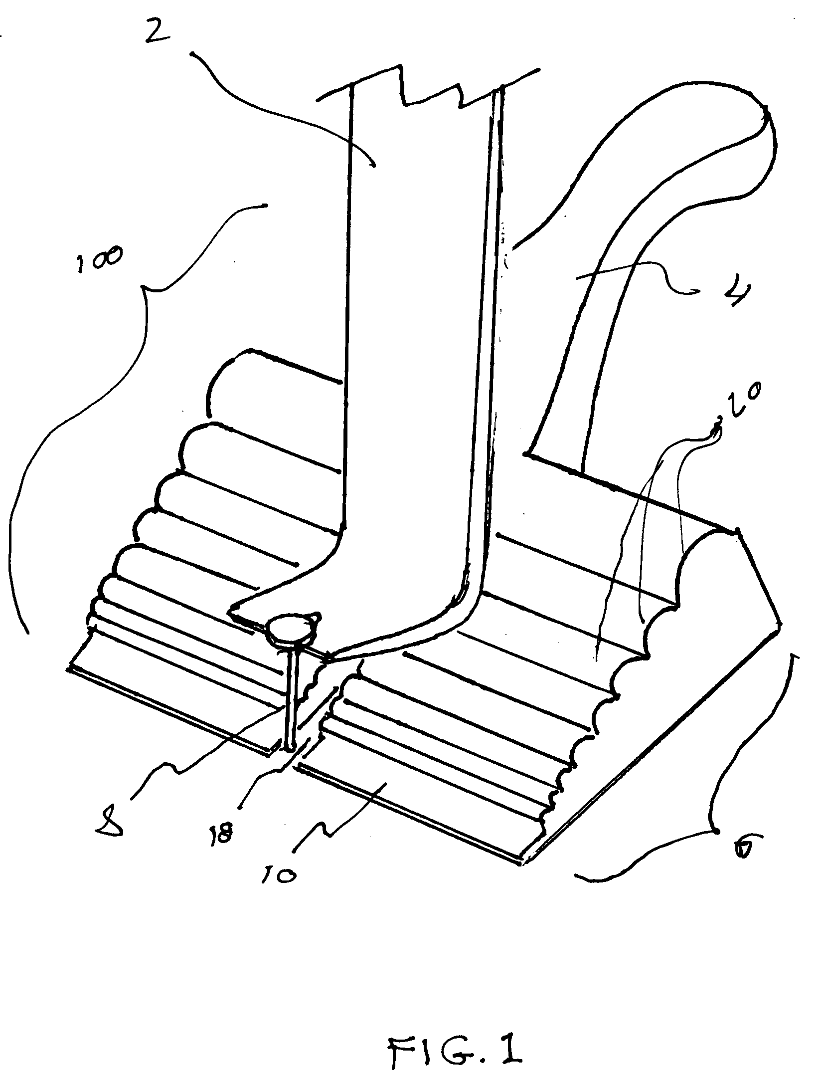
[0021] Referring now to FIG. 1 we see a perspective view of the invention 100. The invention is comprised of a wedge shape 6 and an attached handle 4. The wedge shape has a slot 18 extending from the front portion of the wedge to the center of the wedge. The top surface of the wedge includes rounded ridges 20 that can help stabilize a nail removal tool such as a pry bar 2 or crow bar or claw portion of a hammer. The wedge shape 6 and slot 18 allows the user to position the pry bar 2 at the ideal height for a given circumstance such...


PUM


Abstract

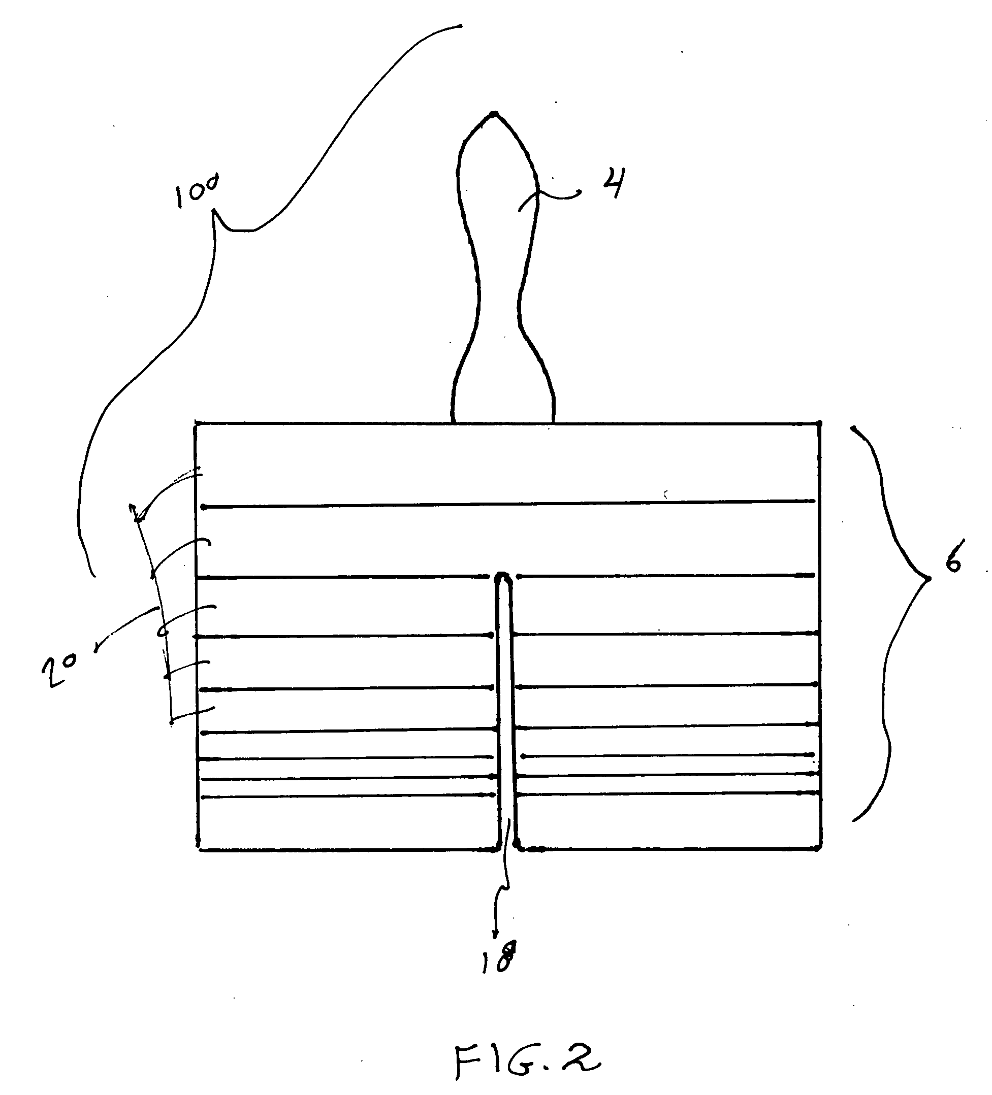
Displaced force backing wedge with a rigid wedge shape, a rigid handle, the wedge shape having a plurality of rounded ridges extending from left to right at its top most surface. The wedge shape has a centrally located slot extending perpendicularly from the thin edge of the wedge to the center area of the wedge. The handle extends outward perpendicularly from a central portion of the thick side of the wedge. A preferred embodiment includes rounded ridges that run parallel to the front surface and start as a small radius and progress to larger radius.

Description

CROSS REFERENCE TO RELATED APPLICATIONS [0001] Not Applicable STATEMENT REGARDING FEDERALLY SPONSORED RESEARCH OR DEVELOPMENT [0002] Not Applicable DESCRIPTION OF ATTACHED APPENDIX [0003] Not Applicable BACKGROUND OF THE INVENTION [0004] This invention relates generally to the field of carpenter tools and more specifically to a displaced force backing wedge. [0005] Often during the process of building or reconstructing a home, office or other structure it becomes necessary to pry loose and remove a nail or trim board or other building materials with a crow bar, claw hammer or other removal tools. Unfortunately, during the process, the surrounding wall surface such as sheet rock or relatively soft wood can become marred by the removal tool because the opposing force exerted by the underside of the removal tool is located in a relatively small area and can thereby cause dents or marring. This causes extra work for the user because the dents or mars have to be filled and refinished. [0...

Claims


Application Information

Patent Timeline
IPC IPC(8): B66F13/00
CPCB25C11/00
Inventor LAWSON, JEFFREY G.
Owner LAWSON JEFFREY G
Learn More