
Gantry crane

A gantry crane and front support technology is applied to the gantry crane. It can solve the problems of not being able to adjust the height vertically, unable to adapt to any height places, etc., and achieve the effect of increasing and decreasing the height.

Inactive Publication Date: 2015-01-07
太仓市金达机械厂
View PDF5 Cites 2 Cited by
  • Summary
  • Abstract
  • Description
  • Claims
  • Application Information

AI Technical Summary

Problems solved by technology

[0002] As we all know, gantry cranes are also called gantry cranes, which are mainly used for loading and unloading operations in indoor or outdoor freight yards, stock yards, and bulk cargoes; its metal structure is like a door-shaped frame, and two legs are installed under the main beam, which can be directly on the ground. Walking on the track, both ends of the main girder can have outrigger cantilever beams; gantry cranes have the characteristics of high site utilization, large operating range, wide adaptability, and strong versatility, and are widely used in port freight yards; existing gantry cranes include Left front support, left rear support, right front support, right rear support, crossbeam and slide rail, the tops of left front support, left rear support, right front support and right rear support are all fixed with crossbeam, described left front support, left rear support, right front support and the bottom of the right rear bracket are provided with pulleys, the slide rails are installed below the pulleys, and the pulleys and the slide rails are slidably matched; the crossbeam is provided with a motor, and the output end of the motor is provided with a transmission wheel group, and the transmission wheel The output end of the gantry crane is provided with a transmission chain, and a hook is provided at the output end of the transmission chain; it is found in the use of this kind of gantry crane that it cannot adjust the height vertically, so it cannot achieve the purpose of adapting to any height.

Method used


Image

  • Gantry crane
  • Gantry crane
  • Gantry crane

Examples


Embodiment Construction

[0011] The specific implementation manners of the present invention will be further described in detail below in conjunction with the accompanying drawings and embodiments. The following examples are used to illustrate the present invention, but are not intended to limit the scope of the present invention.

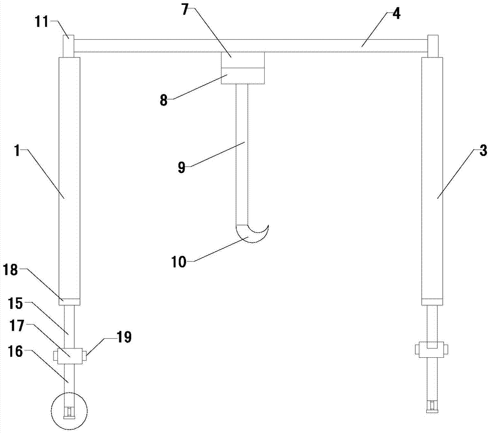
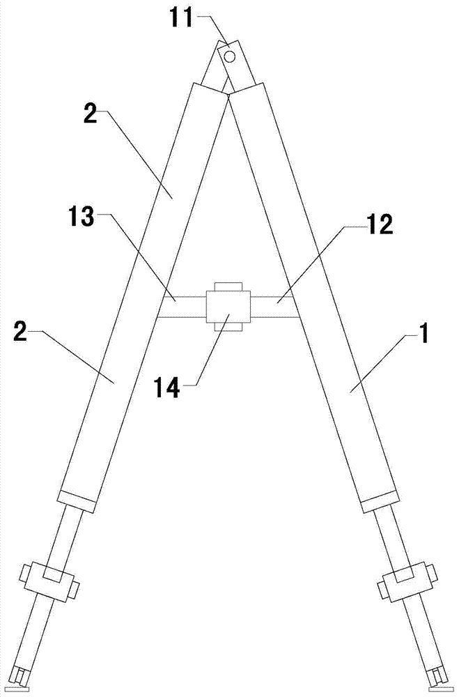
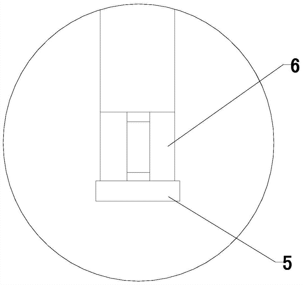
[0012] Such as figure 1 and figure 2 As shown, the gantry crane of the present invention comprises a left front support 1, a left rear support 2, a right front support 3, a right rear support, a beam 4, a slide rail 5 and a pulley 6, and the slide rail is installed under the pulley, and the pulley and the slide rail slide Cooperate; the beam is provided with a motor 7, and the output end of the motor is provided with a transmission wheel set 8, the output end of the drive wheel set is provided with a transmission chain 9, and a hook 10 is provided at the output end of the transmission chain; the left front bracket, the left The tops of the rear bracket, the right front ...


PUM


Abstract

The invention relates to a gantry crane which can be conveniently subjected to longitudinal height adjustment, relating to the technical field of lifting equipment. The gantry crane comprises a left front bracket, a left rear bracket, a right front bracket, a right rear bracket, a crossbeam, sliding rails, pulleys, a first connecting bar, a second connecting bar, a third connecting bar, a fourth connecting bar, a left sleeve, a right sleeve, lower support legs and lower sleeves, wherein the sliding rails are mounted under the pulleys and are in sliding fit with the pulleys; a motor is arranged on the crossbeam, a transmission wheel set is arranged at the output end of the motor, a transmission chain is arranged at the output end of the transmission wheel set, and a hook is arranged at the output end of the transmission chain; connecting sheets are arranged at the top ends of the left front bracket, the left rear bracket, the right front bracket and the right rear bracket, through holes are formed in the connecting sheets, and the left front bracket, the left rear bracket, the right front bracket and the right rear bracket can oppositely rotate; upper support legs are arranged at the bottom ends of the left front bracket, the left rear bracket, the right front bracket and the right rear bracket.

Description

technical field [0001] The invention relates to the technical field of hoisting equipment, in particular to a gantry crane. Background technique [0002] As we all know, gantry cranes are also called gantry cranes, which are mainly used for loading and unloading operations in indoor or outdoor freight yards, stock yards, and bulk cargoes; its metal structure is like a door-shaped frame, and two legs are installed under the main beam, which can be directly on the ground. Walking on the track, both ends of the main girder can have outrigger cantilever beams; gantry cranes have the characteristics of high site utilization, large operating range, wide adaptability, and strong versatility, and are widely used in port freight yards; existing gantry cranes include Left front support, left rear support, right front support, right rear support, crossbeam and slide rail, the tops of left front support, left rear support, right front support and right rear support are all fixed with cr...

Claims


Application Information

Patent Timeline
IPC IPC(8): B66C19/00B66C5/02
CPCB66C19/00B66C5/02B66C2700/01
Inventor 高安祥吴琴秀
Owner 太仓市金达机械厂
Learn More