System and method of confirming lubrication to bearing

a technology of lubricant flow and system, applied in the direction of liquid/fluent solid measurement, volume metering, instruments, etc., can solve the problems of obtaining a useful analysis of whether the bearings are functioning properly, the failure of pressure measurement of the pump to indicate a malfunctioning system, and the deficiency of lubrication system technology

Active Publication Date: 2016-10-06
LINCOLN INDUSTRIES CORP
View PDF4 Cites 8 Cited by
  • Summary
  • Abstract
  • Description
  • Claims
  • Application Information

AI Technical Summary

Problems solved by technology

Several factors prevent obtaining a useful analysis of whether the bearings are functioning properly, such as the temperature dependent properties of the lubricant, or the malfunctioning (e.g. jamming) of lubrication valves caused by contaminants in the lubricant flow.
In these instances, a pressure measurement of the pump may fail to indicate a malfunctioning system.
Many current technologies related to lub

Method used


Image

  • System and method of confirming lubrication to bearing
  • System and method of confirming lubrication to bearing
  • System and method of confirming lubrication to bearing

Examples


Embodiment Construction

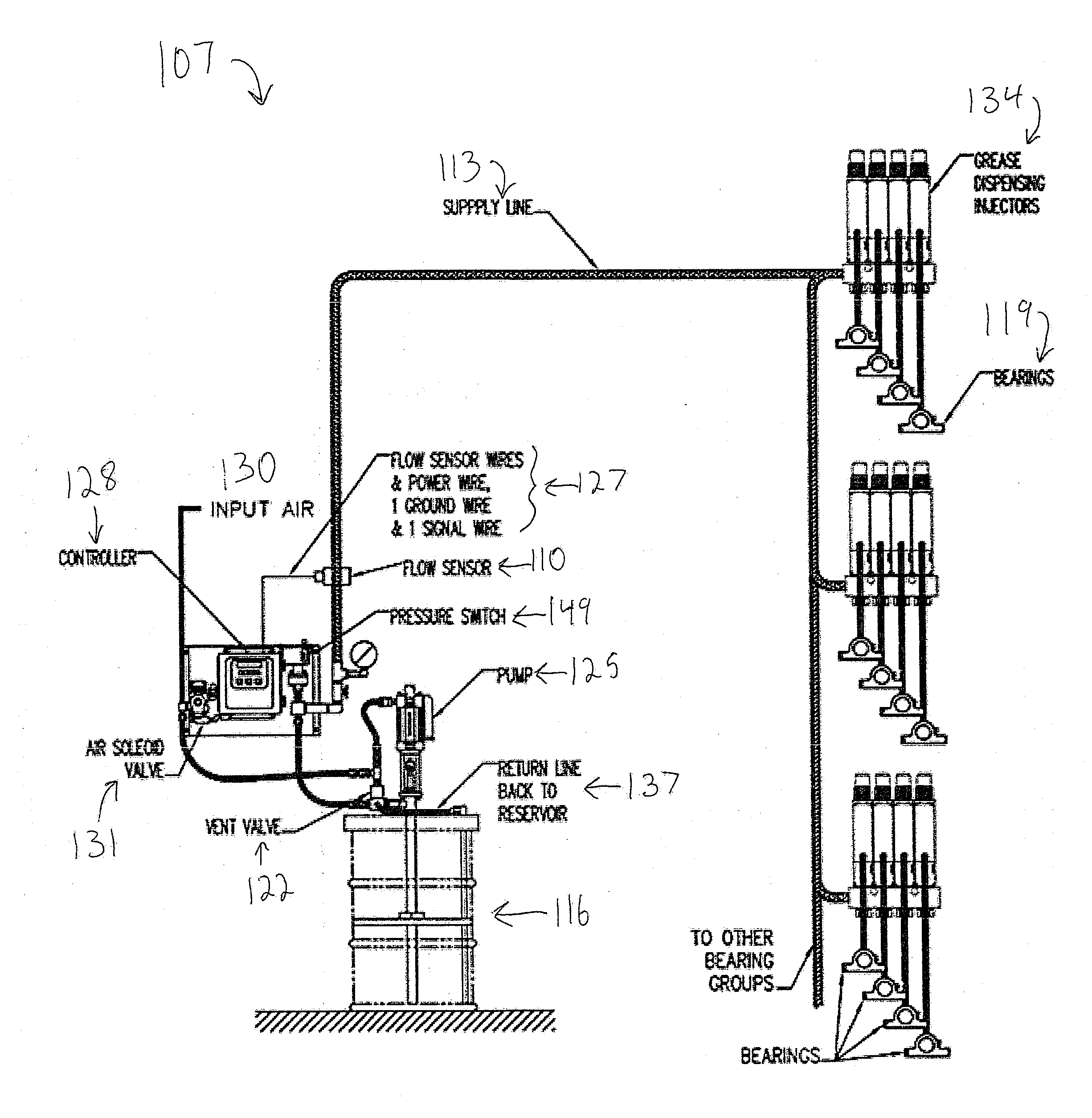
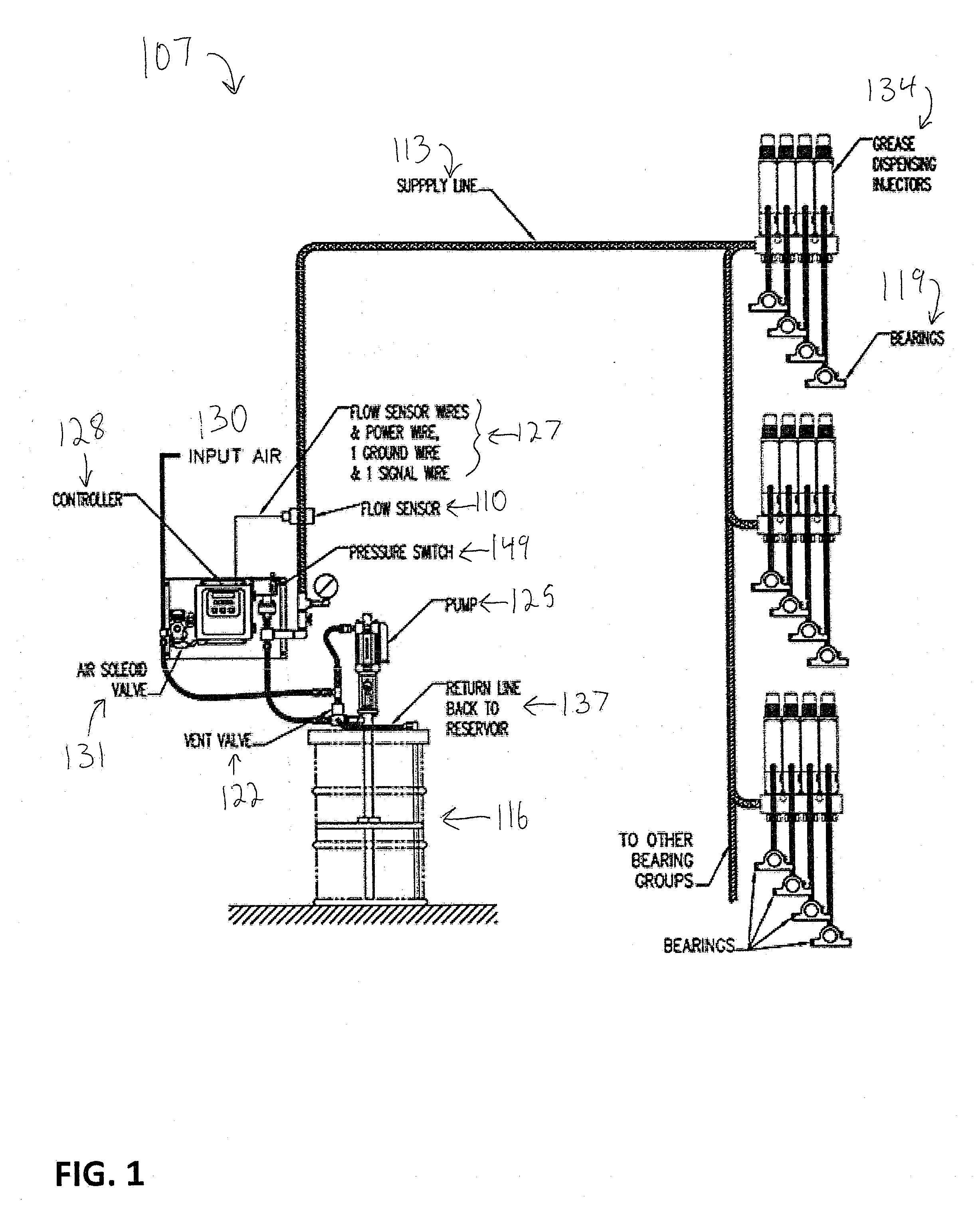
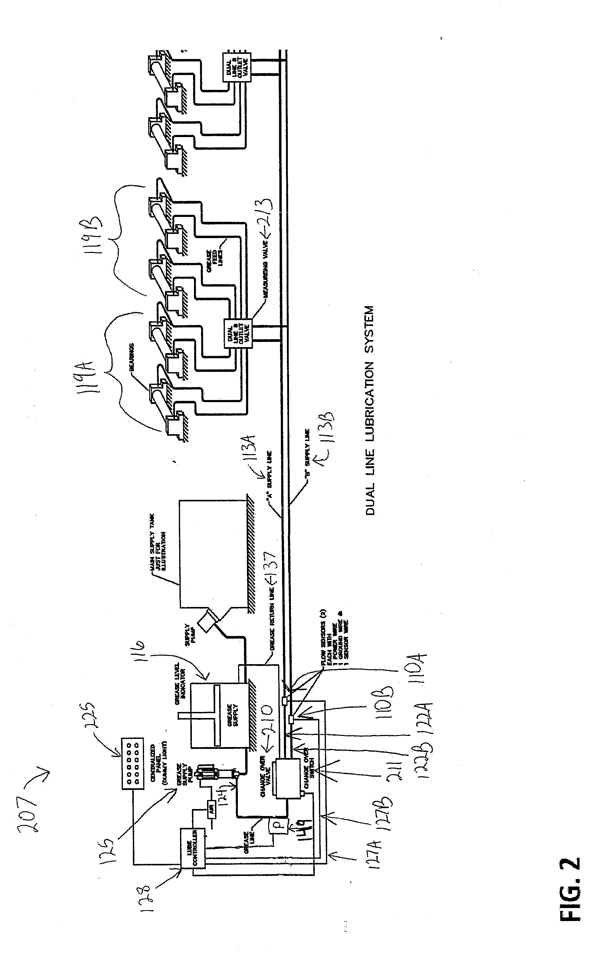
[0011]Certain terminology is used in the following description for convenience only and is not limiting. The words “right”, left”, “lower”, “upper”, “upward”, “down” and “downward” designate directions in the drawings to which reference is made. The words “inner”, “inwardly” and “outer”, “outwardly” refer to directions toward and away from, respectively, a designated centerline or a geometric center of an element being described, the particular meaning being readily apparent from the context of the description. Further, as used herein, the word “connected” is intended to include direct connections between two members without any other members interposed therebetween and indirect connections between members in which one or more other members are interposed therebetween. Furthermore, the term “fluid” as used herein is intended to include both liquids and semi-solids capable of being transported through a passage, a channel, a tube or similar structure, and the term “flow” is intended ...


PUM


Abstract

Methods and systems for determining lubrication flow dispensed to lubrication points. Lubricant delivery is determined based upon the difference between volume measurements detected as the lubricant is delivered to the lubrication points, and volume measurements detected as the lubricant is vented after delivery. A flow sensor in the lubricant supply line measures lubricant delivered and lubricant vented and a controller determines the amount dispensed based upon the difference between the delivered and vented measurements.

Description

BACKGROUND OF THE INVENTION[0001]The present invention relates to systems and methods of confirming lubricant flow, and particularly to systems and methods for measuring the net flow of highly viscous lubricant to confirm sufficient lubricant flow to bearings.[0002]Automatic lubrication systems are pressure activated systems that distribute lubricant. Examples known in the art include single line injector systems and dual line lubrication systems. Flow sensors are commonly used in presently available automatic lubrication systems to detect whether the lubrication system is functioning properly. The flow sensors are typically placed in lines that supply lubricant to the system. One indication that the system is functioning properly is the indication of adequate flow sensed by the flow sensors. Another common indication that the system is functioning properly is provided by measuring the pressure of the pump supplying lubricant to the system. Lubrication points, or bearings, are a cri...

Claims


Application Information

Patent Timeline
IPC IPC(8): G01F3/00F16N31/00F16N13/22
CPCG01F3/00F16N31/00F16N13/22F16N7/385F16N13/16F16N29/00F16N2250/06G01F15/008
Inventor CONLEY, PAUL G.DONOVAN, NATHAN DAVID
Owner LINCOLN INDUSTRIES CORP
Why Eureka
Try Eureka