Eureka AIR delivers breakthrough ideas for toughest innovation challenges, trusted by R&D personnel around the world.

Hitch ball mount and method of forming the hitch ball mount

Active Publication Date: 2016-10-13
HORIZON GLOBAL AMERICAS INC
View PDF15 Cites 1 Cited by
  • Summary
  • Abstract
  • Description
  • Claims
  • Application Information

AI Technical Summary

Benefits of technology

The patent describes a hitch ball mount that can securely attach a hitch ball to a towing vehicle's hitch receiver. It consists of a tubular body with a cavity between its ends, with the first end connected to the hitch receiver. There is also a drop portion that is continuous with the tubular body and formed between the first and second ends. The drop portion has a mounting portion at the second end of the tubular member, which is free of the cavity. The technical effects of this design include more secure attachment of the hitch ball to the vehicle and reduced likelihood of damage or malfunction during towing.

Problems solved by technology

This may result in the trailer hitch ball mount being carried and manipulated by a user when he or she desires to attach or remove the hitch ball.
During use of the trailer hitch ball mount, however, significant forces are applied.
This may result in the trailer hitch ball mount being heavy and difficult for a user to manipulate.
Moreover, the traditional hitch ball mount must go through several different steps in manufacturing, which may result in a higher cost to manufacture.
The additional processing required to weld the components together adds to the time and costs to manufacture the hitch ball mount.

Method used


Image

  • Hitch ball mount and method of forming the hitch ball mount
  • Hitch ball mount and method of forming the hitch ball mount
  • Hitch ball mount and method of forming the hitch ball mount

Examples


Embodiment Construction

[0092]Reference will now be made in detail to exemplary embodiments of the present invention, examples of which are illustrated in the accompanying drawings. It is to be understood that other embodiments may be utilized and structural and functional changes may be made without departing from the respective scope of the invention. Moreover, features of the various embodiments may be combined or altered without departing from the scope of the invention. As such, the following description is presented by way of illustration only and should not limit in any way the various alternatives and modifications that may be made to the illustrated embodiments and still be within the spirit and scope of the invention.

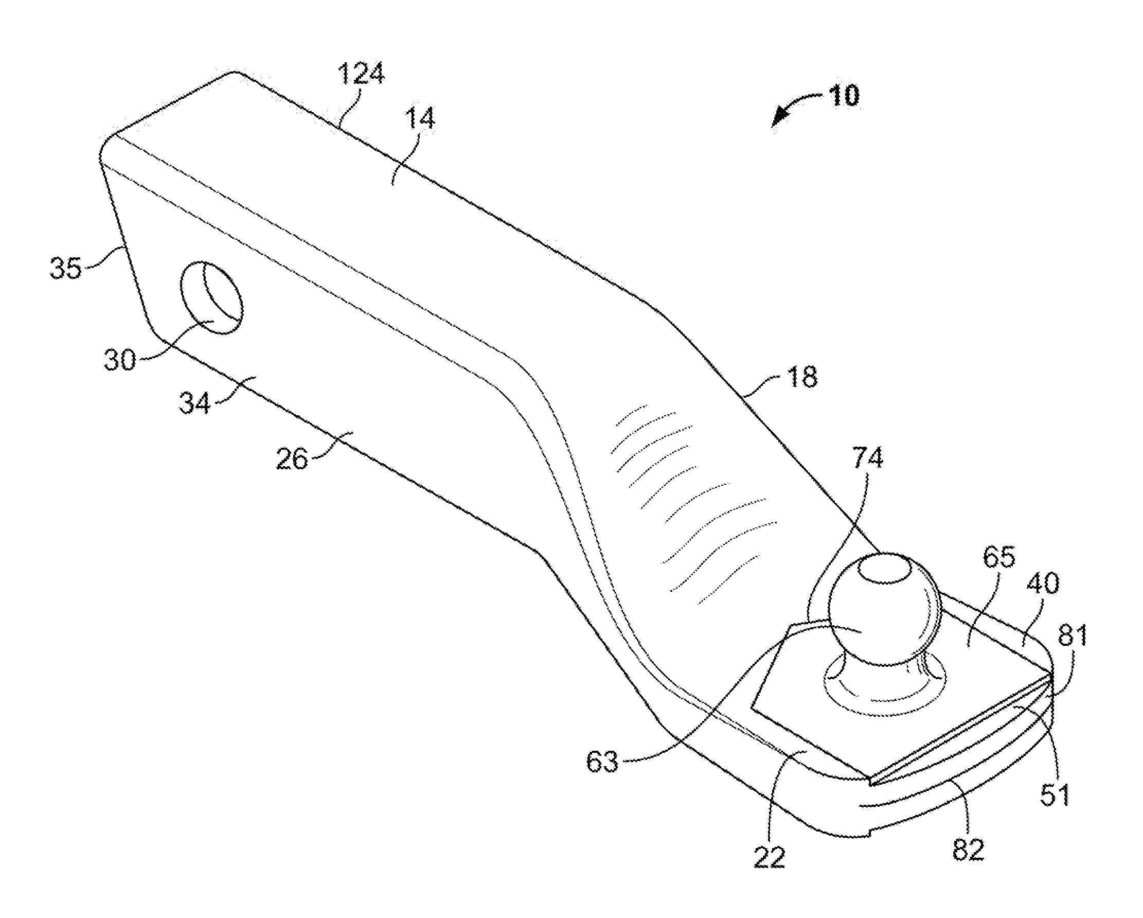
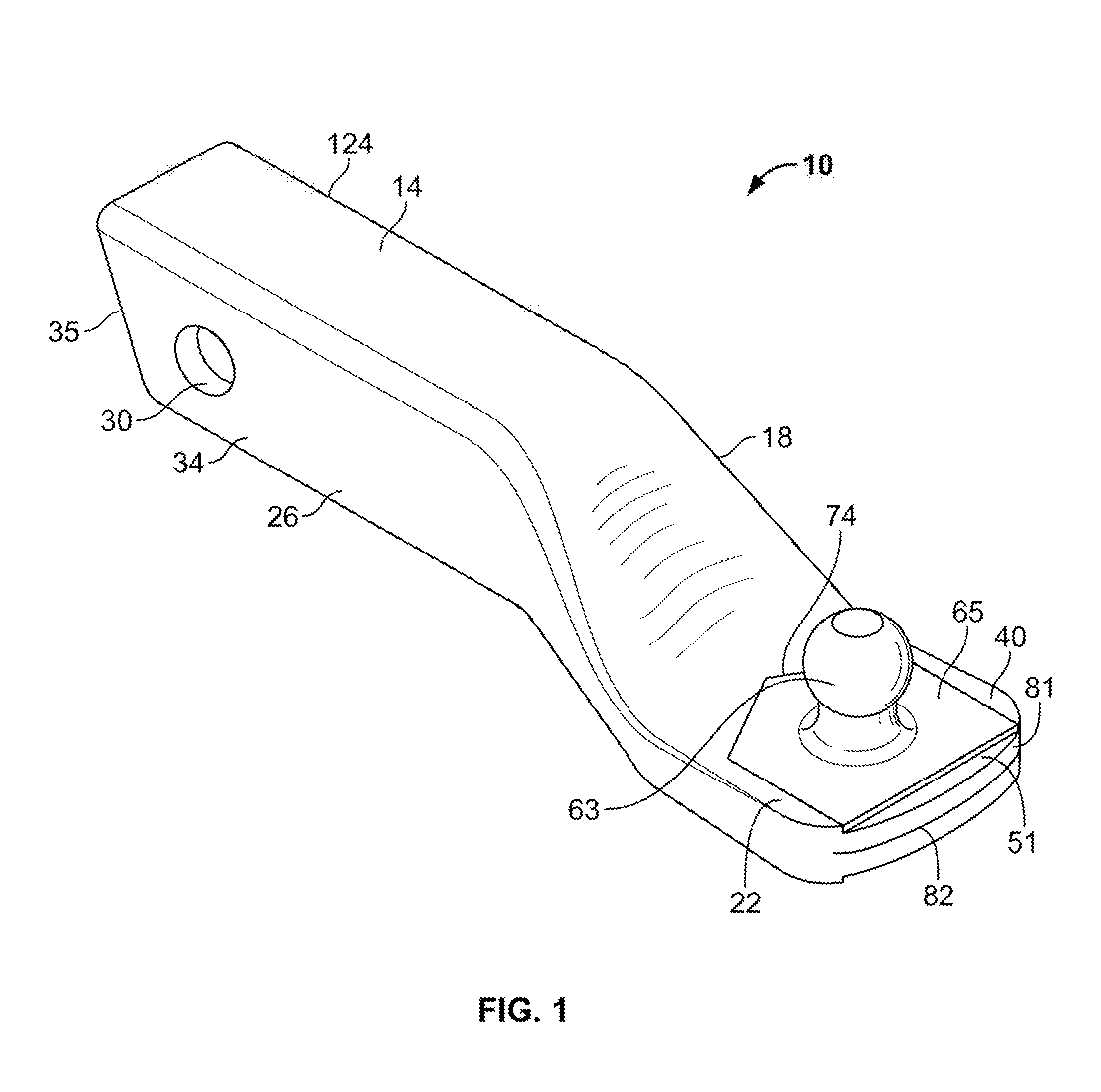
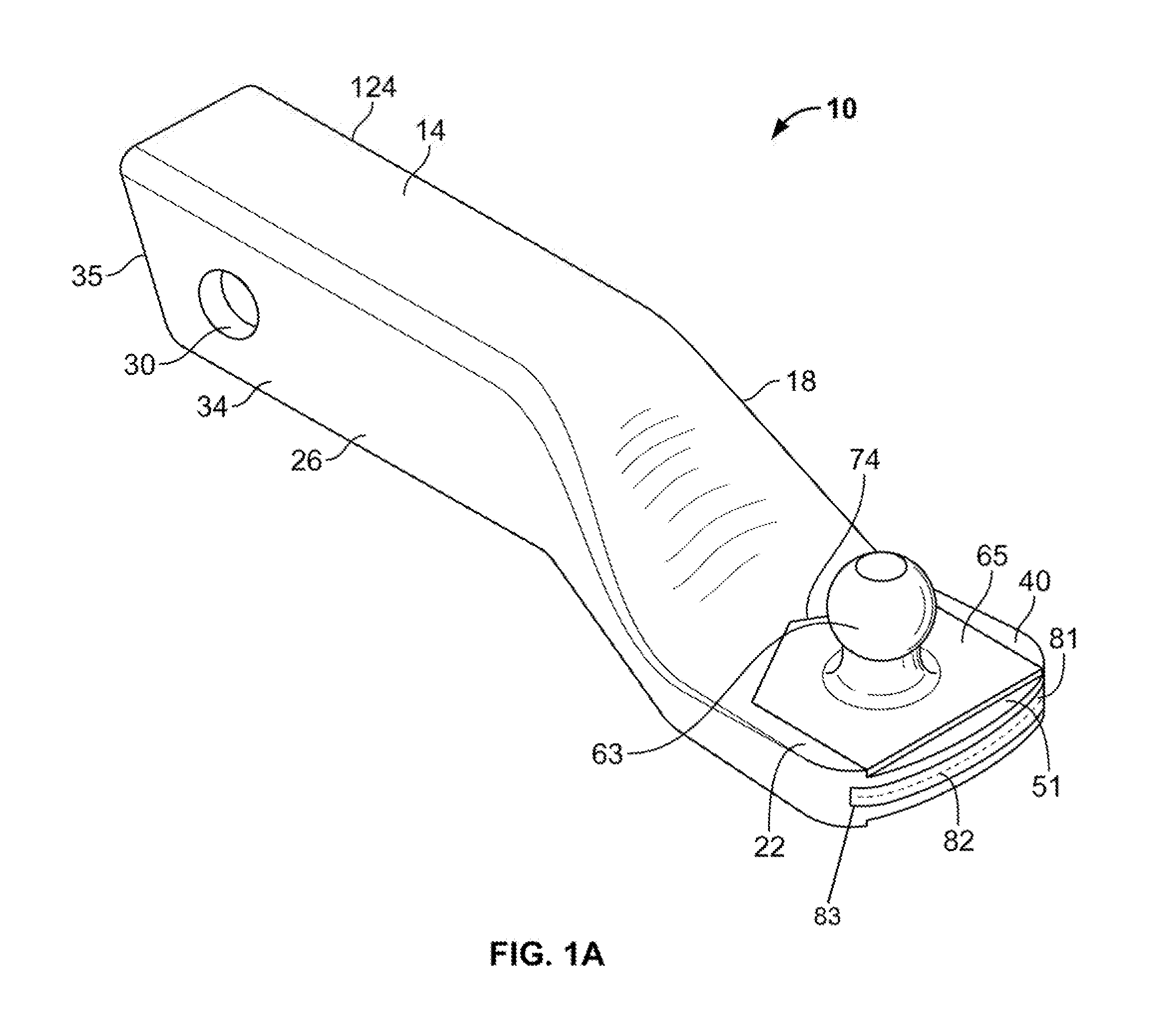
[0093]A hitch ball mount 10 may be utilized to operatively secure a towing vehicle 12 with a towed vehicle in any appropriate manner. The hitch ball mount 10 may be formed as a monolithic unit or otherwise may be integrally formed. The hitch ball mount 10 may include a hitch receiver...


PUM


Abstract

A hitch ball mount is shown and described. The hitch ball mount may include a generally tubular body having first and second end portions, the first end portion engageable with a hitch receiver of a towing vehicle, and a drop portion monolithic with the tubular body and formed between the first and second end portions of the tubular member. The hitch ball mount may further include a hitch ball mounting portion monolithic with the drop portion and tubular body, the hitch ball mounting portion formed at the second end portion of the tubular member and extending from the drop portion, where a hitch ball is selectively attachable to the hitch ball mounting portion.

Description

CROSS-REFERENCE TO RELATED APPLICATION[0001]This application is a continuation of U.S. Utility patent application Ser. No. 13 / 649,700, entitled “Hitch Ball Mount and Method of Forming the Hitch Ball Mount” filed on Oct. 11, 2012, which claims the benefit of U.S. Provisional Patent Application No. 61 / 545,878 entitled “Stamped Hitch Ball Mount” filed on Oct. 11, 2011, which is hereby incorporated in its entirety by reference.FIELD OF THE INVENTION[0002]The present invention is generally related to a hitch ball mount and, more particularly, to a stamped hitch ball mount and method of forming a hitch ball mount.BACKGROUND[0003]There are many different kinds of towing systems that are capable of securing a towed vehicle to a towing vehicle. Many of these systems attach in proximity to the rear of the towing vehicle. This results in the towed vehicle being secured to and extending from the rear of such towing vehicle. A common type of rear extending towing system is a trailer hitch receiv...

Claims


Application Information

Patent Timeline
IPC IPC(8): B60D1/06B60D1/52
CPCB60D1/52B60D1/06
Inventor BERNART, FRANCISDEPIETRO, THOMAS
Owner HORIZON GLOBAL AMERICAS INC
Why Eureka
Eureka Blog
Learn More