Generator rotor fretting fatigue crack repair method

a technology of fretting fatigue cracks and generator rotors, which is applied in the field of generator rotors, can solve the problems and achieve the effect of reducing the low and high cycle fatigue life of the rotors

Active Publication Date: 2016-10-20
GENERAL ELECTRIC CO
View PDF8 Cites 1 Cited by
  • Summary
  • Abstract
  • Description
  • Claims
  • Application Information

AI Technical Summary

Benefits of technology

[0005]This invention provides a process for repairing a generator rotor which has fretting fatigue damage in the rotor teeth at the butt joints of steel rotor wedges. The repair process substantially eliminates existing cracks by machining away any damaged material to create a shape which minimally reduces the low and high cycle fatigue life of the rotor.
[0006]In one embodiment, the slot side wall is machined along both a vertical entry surface and a tapered radially outward dovetail surface to form a single groove that removes the damaged material. The machined areas are concave in shape in a manner that only minimally reduces the low and high cycle fatigue life of the rotor.
[0008]Future fretting damage is substantially eliminated not only by removing the damaged material, but also by replacing the original steel wedges with similarly sized aluminum wedges. This solution is advantageous in that it does not require large scale machining or a high speed rotor balance operation, and is therefore suitable for implementation on site. When the wedges are replaced, the butt joint between adjacent wedges may be aligned with, or offset from the repaired area.
[0010]In another aspect of the present invention a method is provided of servicing, or repairing a crack in, at least one side of a dovetail portion of a rotor coil slot wall in a generator. The rotor coil slot wall includes a radial entry surface connected to an inwardly tapered surface, and the inwardly tapered surface is connected to an intermediate radial surface. The radial entry surface and the intermediate radial surface are substantially parallel to each other. The method includes a first machining step that machines a first groove in the radial entry surface and the inwardly tapered surface. The first groove extends linearly from an outer rotor surface to the intermediate radial surface, and the first groove is configured so that a smooth and linear surface is created along a length of the first groove. A second machining step machines a second groove in the intermediate radial surface in an orientation substantially perpendicular to the first groove and substantially axially with respect to the generator. At least a portion of the second groove contacts a portion of the first groove. At least one of the first groove and the second groove are configured to remove damaged material from the coil slot wall or to act as a preventive measure against damage to the coil slot wall.

Problems solved by technology

The machined areas are concave in shape in a manner that only minimally reduces the low and high cycle fatigue life of the rotor.

Method used


Image

  • Generator rotor fretting fatigue crack repair method
  • Generator rotor fretting fatigue crack repair method
  • Generator rotor fretting fatigue crack repair method

Examples


Embodiment Construction

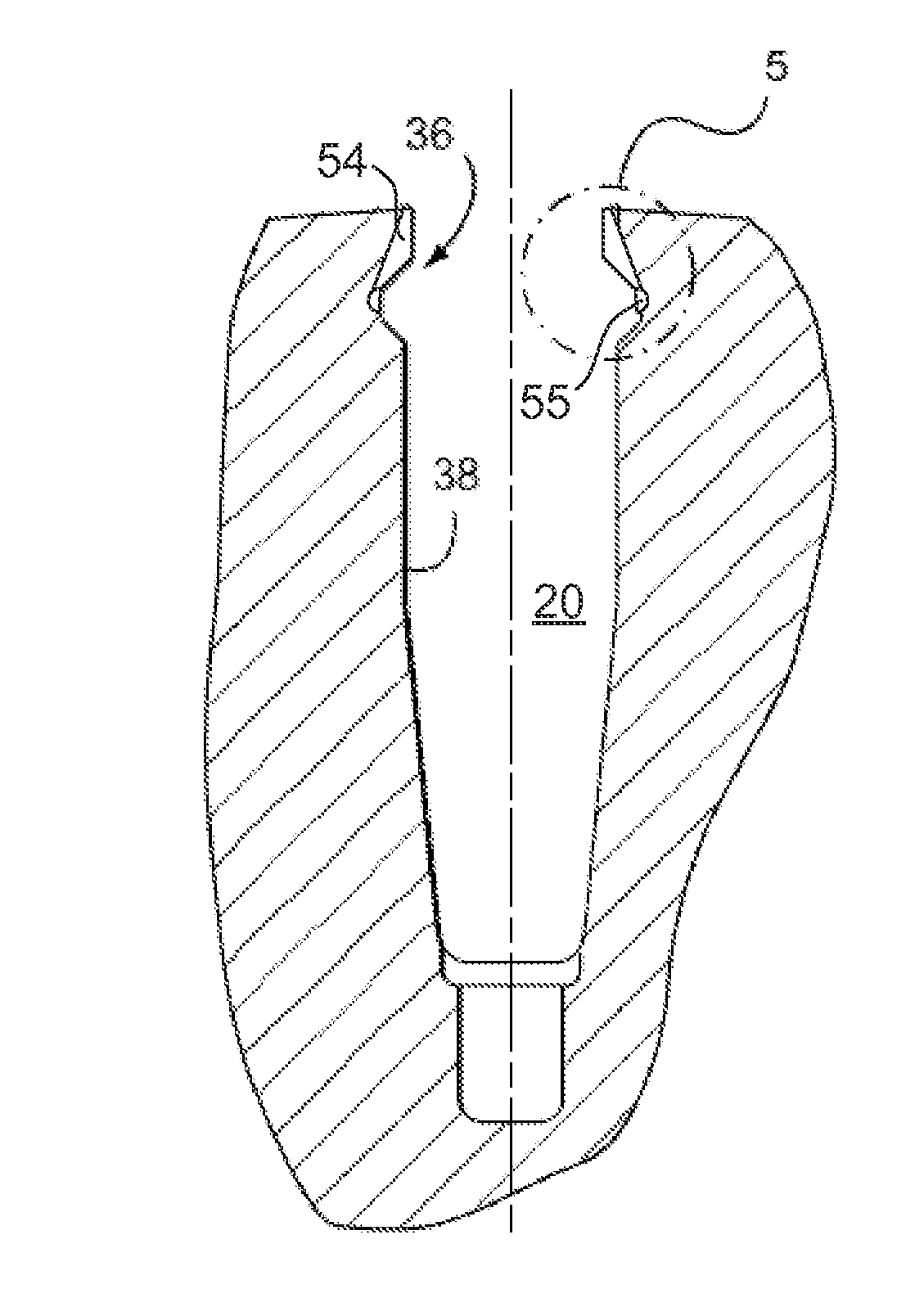
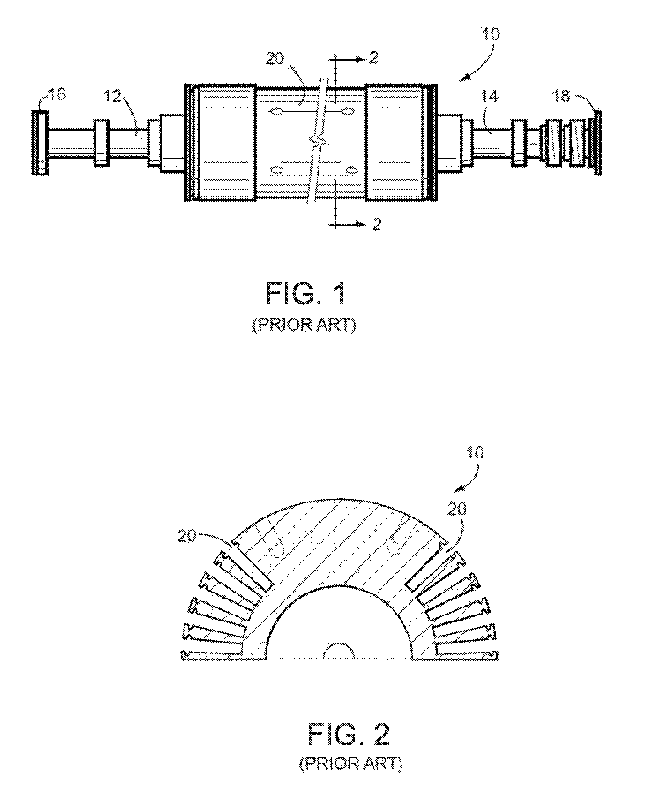
[0020]FIGS. 1 and 2 illustrate a typical rotor 10 for a dynamoelectric machine wherein the rotor includes conventional elements such as rotor end shaft portions 12, 14 and couplings 16, 18 for connection with a turbine or gear reduction unit. Of particular significance here are the axially oriented coil slots 20 arranged circumferentially about the mid-section of the rotor, that are used for holding the copper field windings or coils.

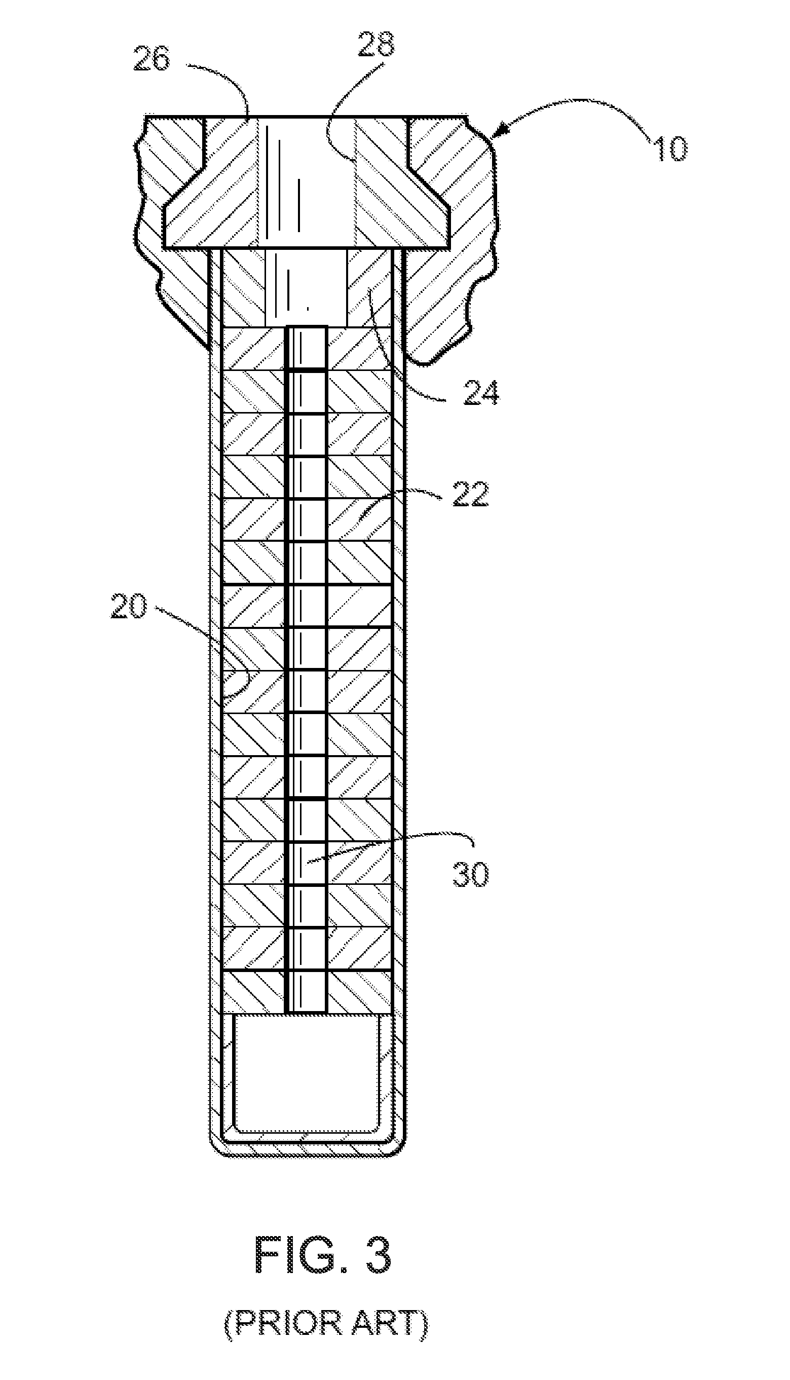
[0021]With farther reference to FIG. 3, the coil slots 20 are each radially directed and typically contain, in a radially outward sequence, insulated copper coils 22, a creepage block 24, and a plurality of axially aligned slot wedges 26. The wedges have a generally dovetail shape in cross section, and are located and arranged so as to maintain the copper coils 22 and creepage block 24 in place while the rotor is spinning. The slot wedges 26 may also contain ventilation holes 28 (one shown) which are in general alignment with ventilation channels 30 (on...


PUM


Abstract

A method of servicing, or repairing a crack in, a dovetail portion of a dynamoelectric machine's rotor coil slot wall. The coil slot wall includes a radial entry surface connected to an inwardly tapered surface. The inwardly tapered surface is connected to an intermediate radial surface. A machining step machines a first groove in the radial entry surface and inwardly tapered surface. The first groove extends linearly to the intermediate radial surface. The first groove is configured so that a smooth and linear surface is created along a length of the first groove. A second machining step machines a second groove in the intermediate radial surface in an orientation substantially perpendicular to the first groove. A portion of the second groove contacts a portion of the first groove. At least one of the first groove and the second groove are configured to remove damaged material from the coil slot wall.

Description

BACKGROUND OF THE INVENTION[0001]This invention relates to generator rotors and specifically, to the repair of generator rotors that have experienced fretting damage and / or cracks in the rotor teeth located at the butt joints of the axially aligned rotor wedges.[0002]Conventional dynamoelectric machines, such as generators used with gas and steam turbines, employ forged rotors of magnetic material into which radial slots are machined for receiving the conductive turns of field windings which are interconnected such as to produce a desired magnetic flux pattern. Typically, included in such conventional rotor slots are creepage blocks at both the top and bottom ends of the slot as well as coil slot wedges for resisting the radially outward forces exerted on the windings when the rotor is operational.[0003]The slot wedges, which are generally dovetail shaped, are used to maintain the copper coils in place while the rotor is spinning at, for example, 3600 revolutions per minute. In the ...

Claims


Application Information

Patent Timeline
Patent Type & Authority Applications(United States)
IPC IPC(8): H02K15/00H02K3/487
CPCH02K3/487H02K15/0006H02K15/024H02K15/0018
Inventor MARSHALL, NATHANIEL PHILIPBECKFORD, ALEXANDER GABRIELBUSKIRK, ERIC STEVEN
Owner GENERAL ELECTRIC CO
Why Eureka
Try Eureka