

Display adjustment methods and head-mounted display devices
- Summary
- Abstract
- Description
- Claims
- Application Information
AI Technical Summary
Benefits of technology
Problems solved by technology
Method used
Image

Examples
first embodiment
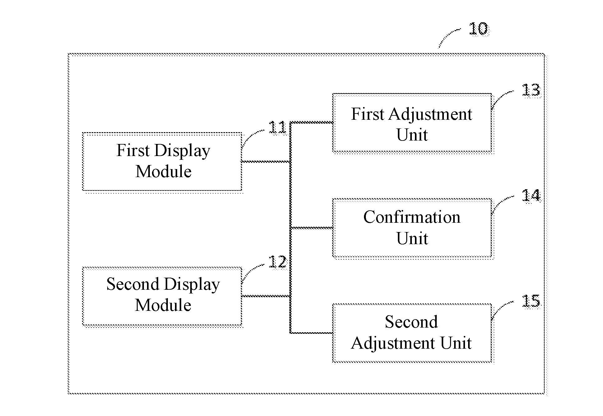
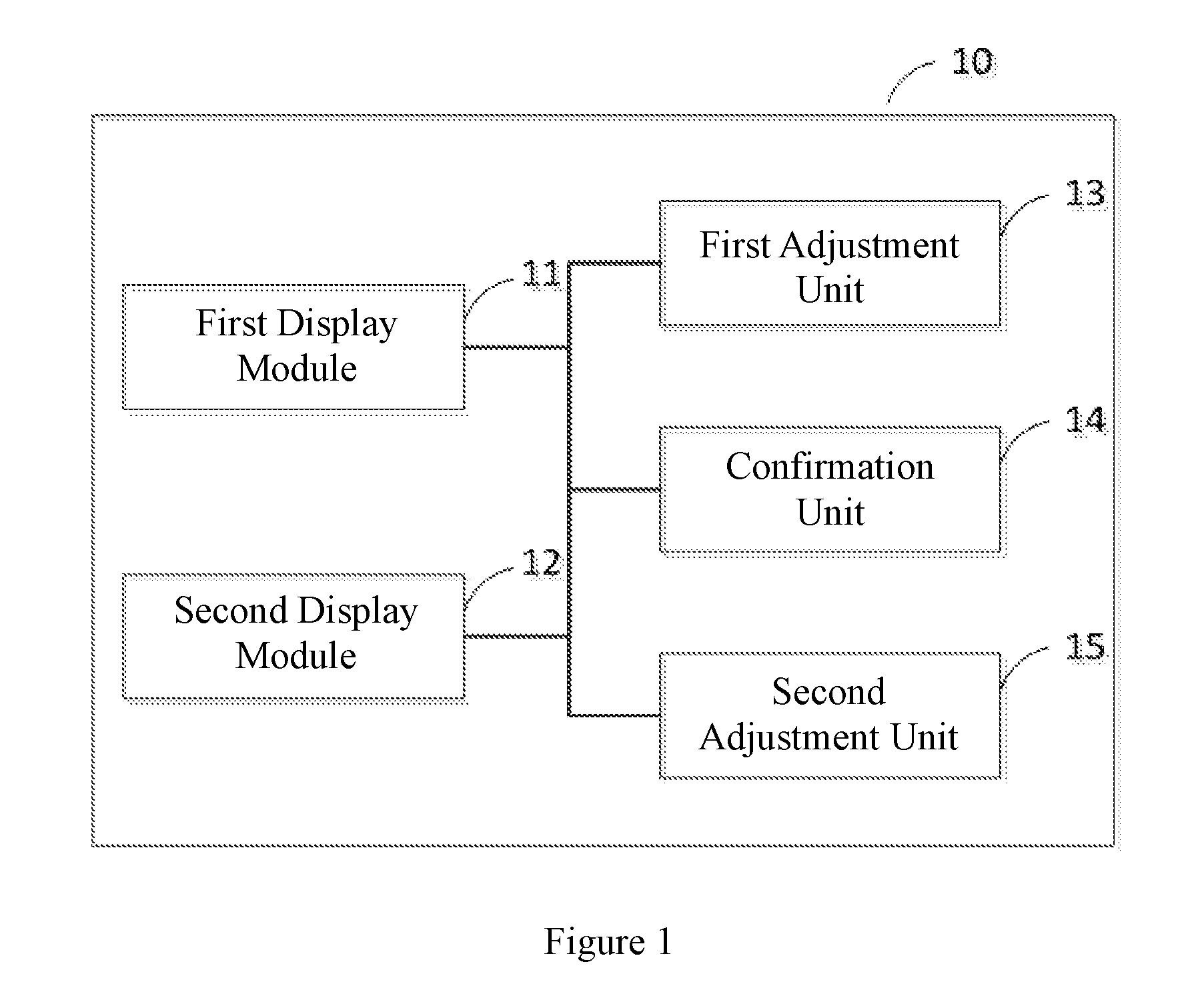
[0024]FIG. 1 is a block diagram for a head-mounted display device according to this disclosure. The head-mounted display device 10 includes: a first display module 11 and a second display module 12.
[0025]The two display modules are respectively used for providing display contents for a user's eyes. Specifically, each display module, i.e., the first display module 11 and the second display module 12, respectively includes a set of micro-display apparatus and an optical module (not shown). Here, the micro-display apparatus is movably connected to one corresponding optical module; that is, a distance between the micro-display apparatus and its corresponding optical module can be adjusted. Images generated by the micro-display apparatuses of the two display modules are respectively projected by their corresponding optical module to a left eye and a right eye of the user in a predetermined direction, and thus the user can see a magnified virtual image for the display contents of the micr...
second embodiment
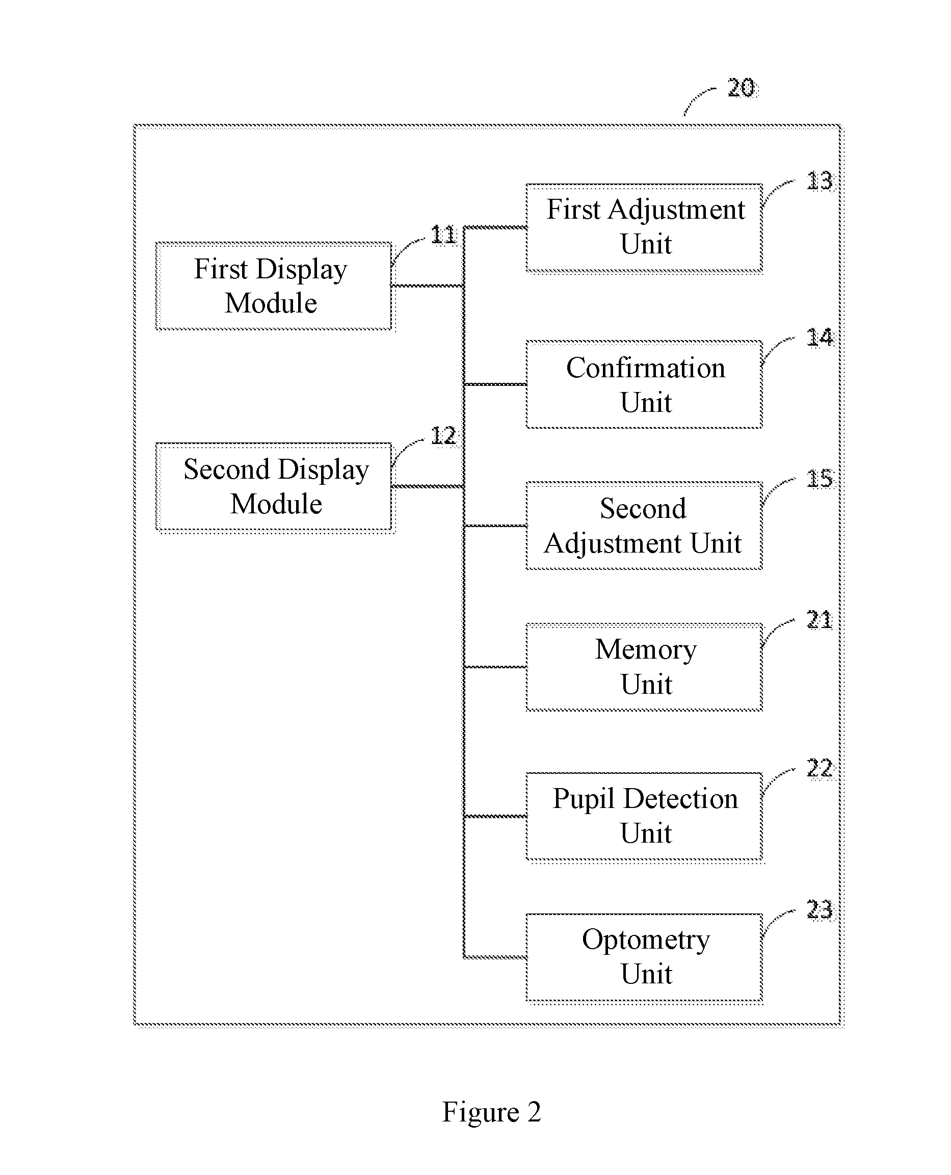
[0046]The head-mounted display device provided in this disclosure provides multiple adjustment modes, and can be set flexibly to further adapt for features and application conditions of different head-mounted display devices.
third embodiment
[0047]FIG. 3 is a block diagram for a head-mounted display device according to this disclosure. In addition to the head-mounted display devices 10 or 20 in the above-described embodiments, the head-mounted display device 30 further includes: a start unit 31 for triggering the first adjustment unit 13 when the head-mounted display device 30 has been powered on.
[0048]Preferably, the start unit 31 can further retrieve and output a start video and / or a start audio before triggering the first adjustment unit 13. The start video and / or the start audio can be pre-stored in the memory unit 21.
[0049]The confirmation unit 14 is also used for: receiving a confirmation signal indicating that both the first adjustment unit 13 and the second adjustment unit 15 have completed the adjustment; and triggering the first display module 11 and the second display module 12 to enter a normal operation mode.
[0050]The head-mounted display device specifically includes but is not limited to head-mounted video...
PUM
 Abstract
Description
Claims
Application Information