Cup for a coffee capsule

a coffee capsule and coffee technology, applied in the field of coffee capsules, can solve the problems of not fully preserving the coffee aroma, prior art cups do not meet, and the weight and production cost of cups are higher, so as to achieve the effect of being effective and robust, being inexpensive to make, and being light in weigh

Pending Publication Date: 2016-12-08
SACMI COOP MECCANICI IMOLA S C R L
View PDF1 Cites 23 Cited by
  • Summary
  • Abstract
  • Description
  • Claims
  • Application Information

AI Technical Summary

Benefits of technology

[0012]It is an aim of the disclosure to provide a cup for a coffee capsule which can create an optimum fluid tight seal with the hood during use. More specifically, the aim is to create a fluid tight seal which remains effective and robust even with variations in the capsule and in the coffee machine, as well as with variations in the shape and size of the pressure hood, in the shape of the capsule and in the centring of the pressure hood and the capsule relative to each other.
[0013]Another aim of the disclosure is to provide a cup for a coffee capsule which is light in weight and inexpensive to make.
[0014]A further aim of the disclosure is to provide a cup for a coffee capsule that can retain to a high degree the aroma of the coffee contained therein.

Problems solved by technology

This is generally obtained by increasing the thickness of the capsule bottom which, however, leads to problems of higher weight and higher production costs on account of the larger amount of material used.
This solution is disadvantageous, however, because it involves additional costs and, in practice, is not fully effective in preserving the coffee aroma up to the moment the beverage is brewed.
Prior art cups do not meet the above mentioned requirements because they do not allow the production of plastic coffee capsules which guarantee high efficiency and reliability of use in coffee machines which perforate the bottoms of the capsules and which hold the cups tightly by the back of the annular flange of the cup itself.

Method used


Image

  • Cup for a coffee capsule
  • Cup for a coffee capsule
  • Cup for a coffee capsule

Examples


Embodiment Construction

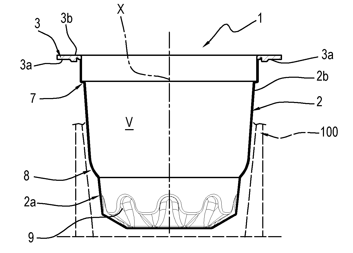
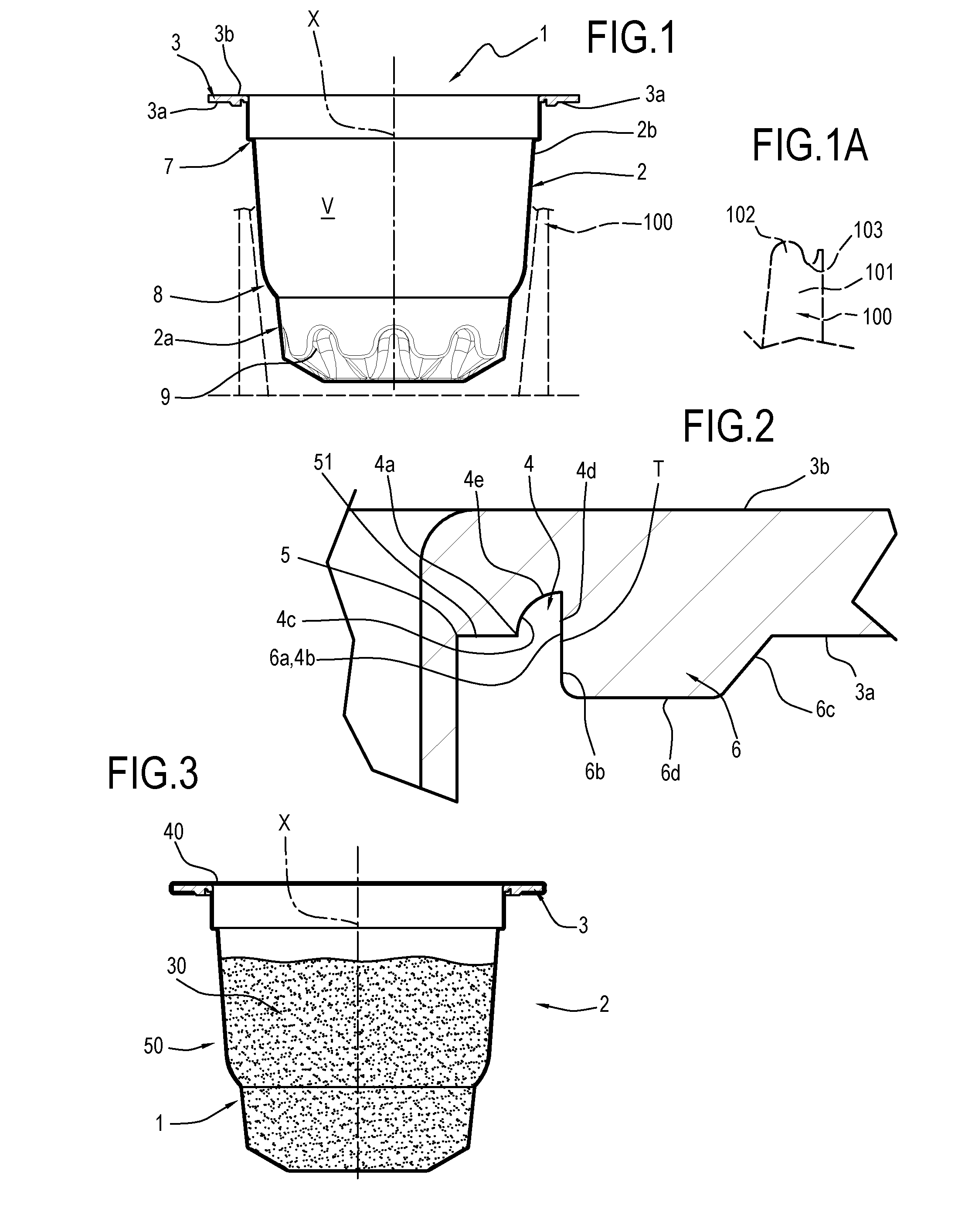
[0037]With reference to the accompanying drawings, the numeral 1 denotes in its entirety a cup for a coffee capsule according to this disclosure.

[0038]The cup 1 is basically made up of two parts: a containment body 2 which internally defines a space “V” open at the top, for containing a dose 30 of coffee powder and which extends between a bottom 2a and an upper edge 2b, and an annular flange 3 located at the upper edge 2b of the containment body 2.

[0039]The annular flange 3 extends around an axis “X” which preferably constitutes an axial axis of symmetry of the containment body 2 and, still more preferably, of the entire cup

[0040]The annular flange 3 lies mainly in a flat plane, perpendicular to the axis “X”.

[0041]The annular flange 3 has a rear (or underside) face 3a, directed towards the containment body 2, and a front (or top) face 3b, adapted to receive a sealing lid / disc 40 applied to it in order to hermetically isolate the dose 30 of coffee inside the space “V” to obtain a cap...


PUM

PropertyMeasurementUnit
angleaaaaaaaaaa
angleaaaaaaaaaa
widthaaaaaaaaaa

Abstract

A cup for a coffee capsule, including a containment body (2) extending between a bottom (2a) and an upper edge (2b) and further including, at the upper edge (2b), an annular flange (3) which extends around an axis (X) and which has a rear face (3a) directed towards the containment body (2) and a front face (3b) adapted to receive a sealing lid (40), where the containment body (2) and the annular flange (3) are defined by a multilayer structure having an inner layer (S1) made of a plastic material, defining the front face (3b) of the annular flange (3) and the inside surface of the containment body (2), an outer layer (S2) made of a plastic material whose hardness is less than that of the inner layer (S1), and an intermediate layer (S3) between the inner layer (S1) and the outer layer (S2) and made of a material impermeable to oxygen and aromas, and where the annular flange (3) has, on its rear face (3a), an annular ridge or tooth (6) and an annular groove (4) which extend around the axis (X) and which are configured to act in conjunction with an end edge (101) of a pressure hood element (100) of a coffee machine.

Description

TECHNICAL FIELD[0001]The present disclosure relates to a cup for a coffee capsule, in particular a cup made of a plastic material, and a machine for making the cup and a coffee capsule comprising the cup.BACKGROUND ART[0002]Known in the prior art (for example, from patent documents WO2012 / 080501, EP2489609, WO2013 / 076519, WO2013 / 136209, US2010 / 288131 and WO2013 / 157924) are coffee capsules comprising a cup of plastic material, filled with a dose of coffee powder and closed by a lid defined by a circular panel sealed onto the cup. The cup has a flat annular flange onto whose front surface the lid is sealed. In use, the coffee capsules are inserted into a specific compartment of a coffee machine equipped with knives for perforating the capsule and with a hood (or lid) configured to clamp down on and seal the annular flange of the capsule in order to brew the coffee according to a method known in the trade of machines of this kind.[0003]In some solutions, the knives intercept the capsul...

Claims


Application Information

Patent Timeline
Patent Type & Authority Applications(United States)
IPC IPC(8): B65D85/804B29C69/02B29B11/10B29C51/08B29C47/06B29C51/14B29C48/21
CPCB65D85/8043B29C47/065B29C51/14B29B11/10B29C51/082B29L2031/7174B29K2023/12B29K2023/06B29K2023/086B29K2995/0067B29C69/02A47J31/4403B29C48/21
Inventor MINGANTI, GIANNI
Owner SACMI COOP MECCANICI IMOLA S C R L
Why Eureka
Try Eureka