Biomedical and pharmaceutical waste sterilizing systems and methods

a biomedical and pharmaceutical waste technology, applied in the field of biomedical and pharmaceutical can solve the problems of large physical size and capital intensive capital expenditure of conventional biomedical waste sterilizing systems and methods

a biomedical and pharmaceutical waste technology, applied in the field of biomedical and pharmaceutical can solve the problems of large physical size and capital intensive capital expenditure of conventional biomedical waste sterilizing systems and methods

US20160361455A1Inactive Publication Date: 2016-12-15ENVIRONTEK WORLDWIDE LLC

Image

  • Biomedical and pharmaceutical waste sterilizing systems and methods
  • Biomedical and pharmaceutical waste sterilizing systems and methods
  • Biomedical and pharmaceutical waste sterilizing systems and methods

Examples


Embodiment Construction

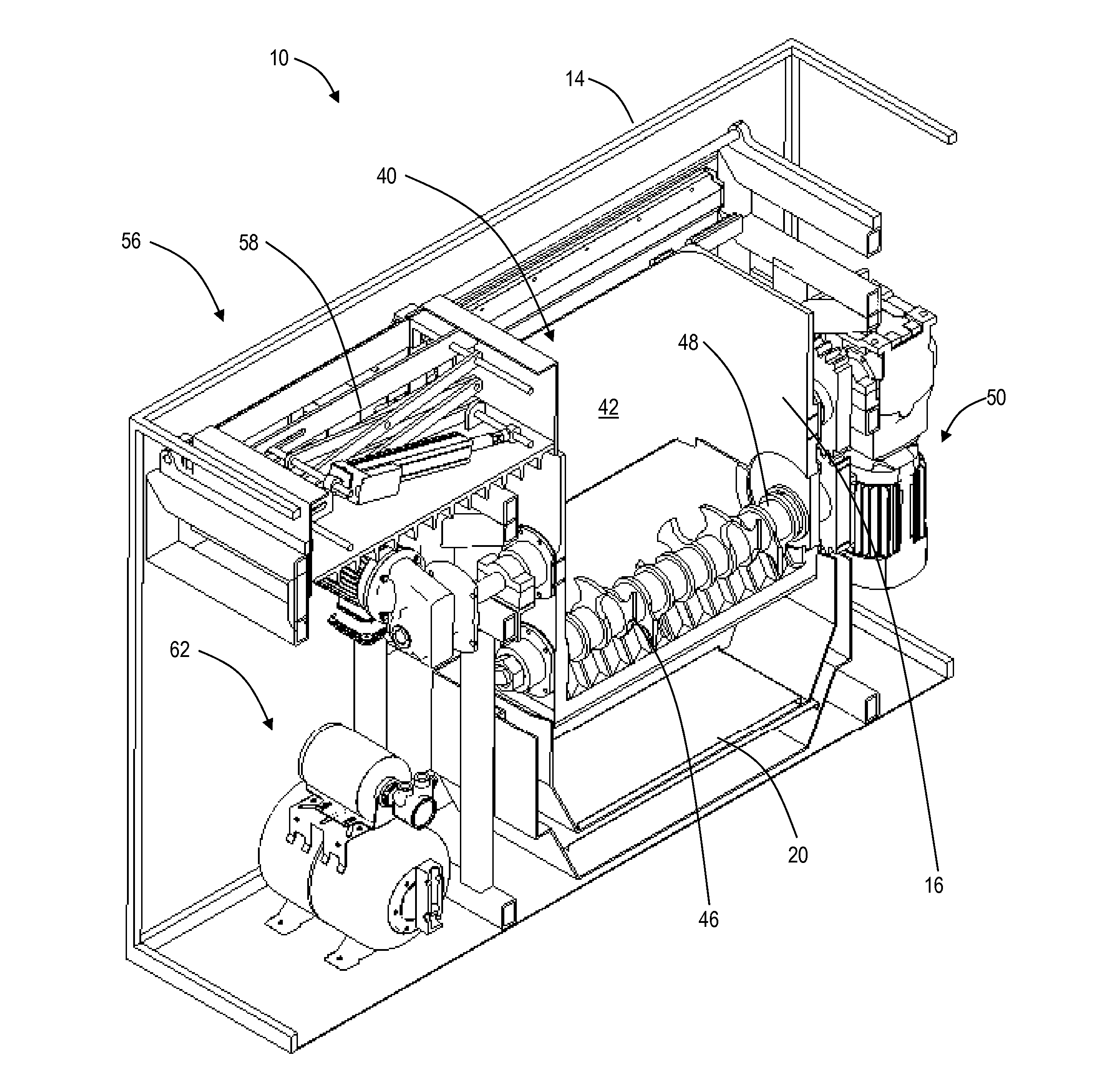
[0026]In various exemplary embodiments, biomedical waste sterilizing systems and methods are described. Particularly, the systems and methods utilize a compact apparatus that is (i) low cost to deploy and operate and (ii) that uses liquid ozone for sterilization / disinfection, while providing better sterilization / disinfection than conventional systems and methods. The cost reduction is based both on a compact design that minimizes capital deployment cost as well as the use of liquid ozone that is generated off-site, avoiding on-site ozone generation equipment.

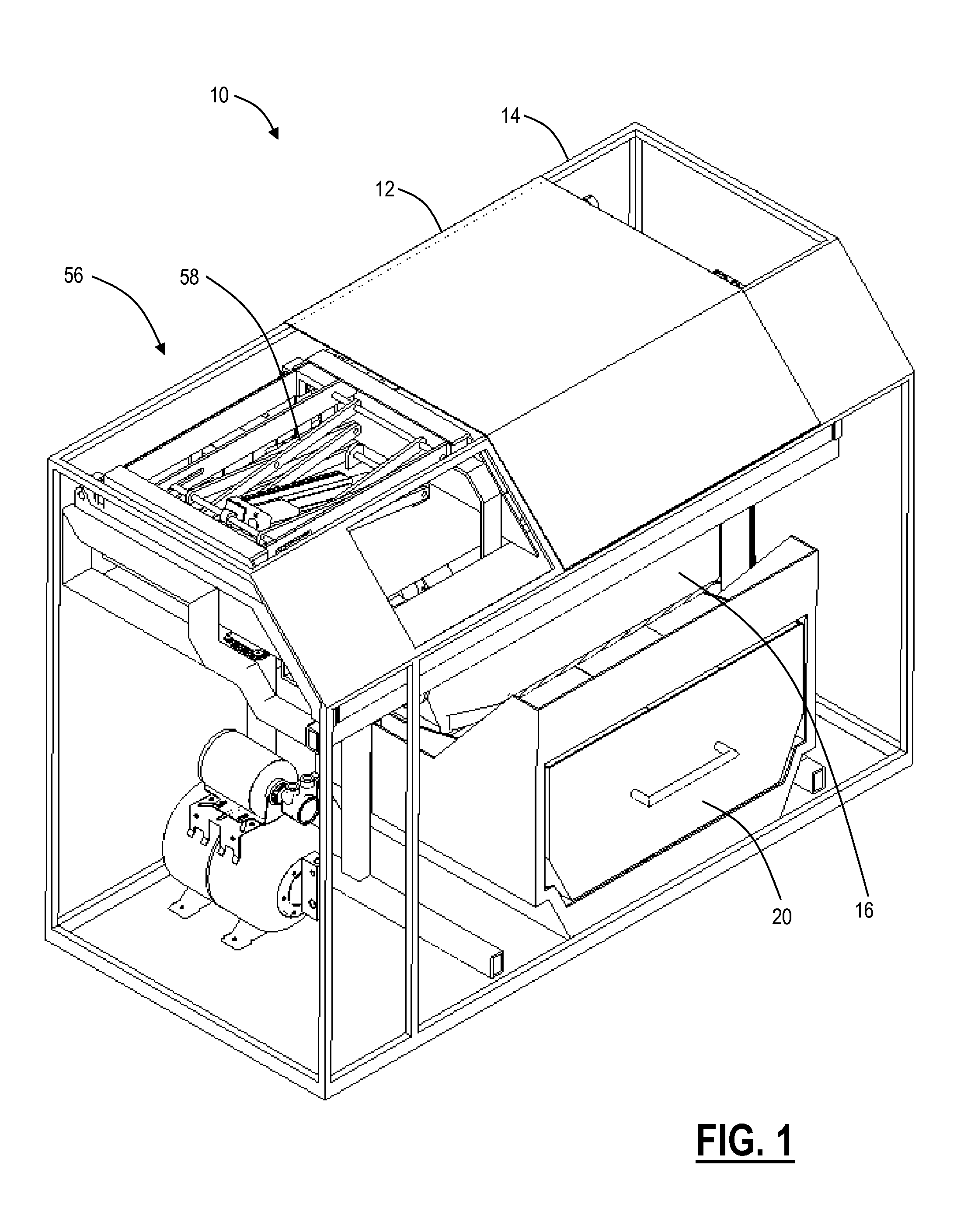
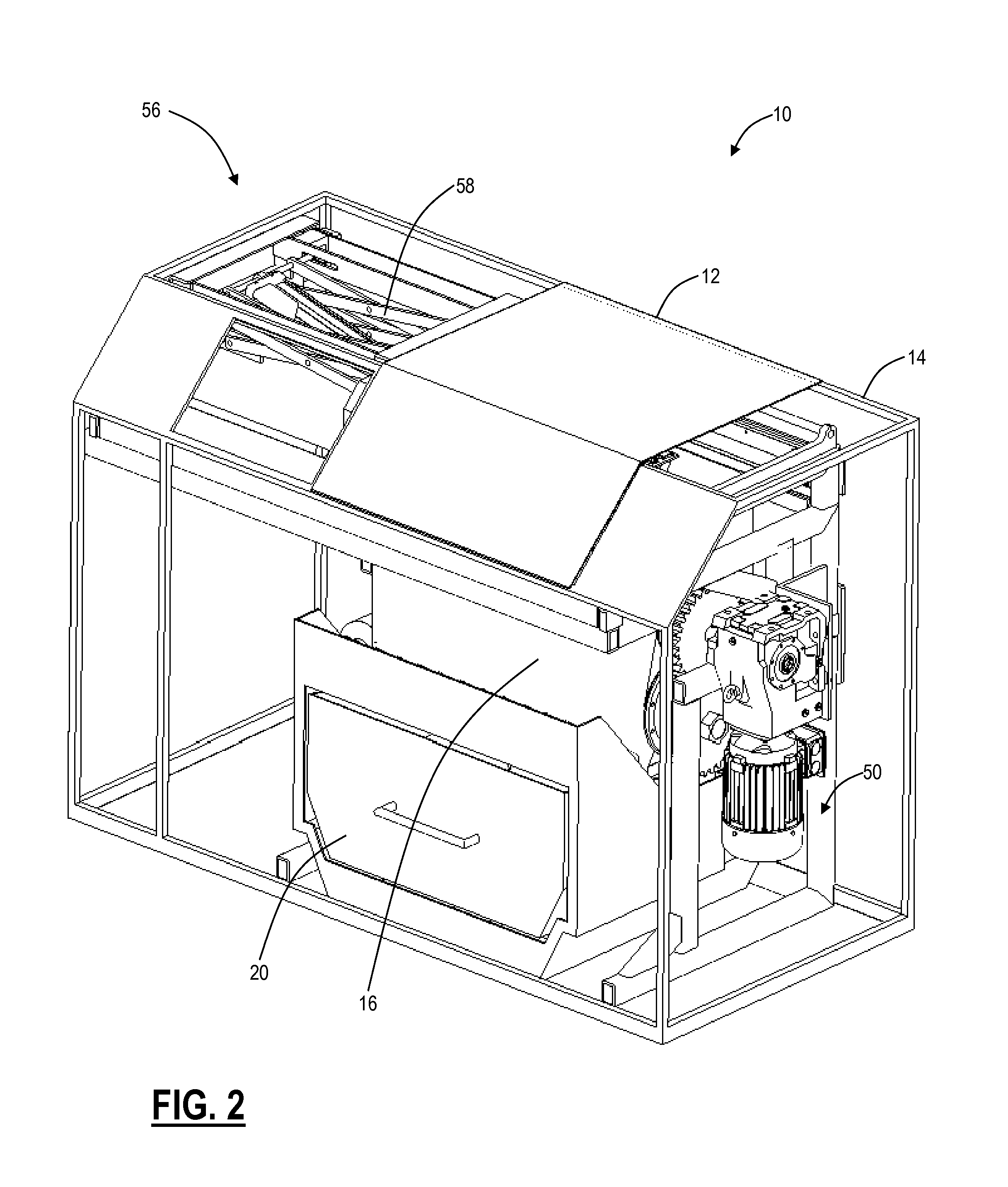
[0027]Referring to FIGS. 1-14, in various exemplary embodiments, various diagrams illustrate a biomedical waste sterilizing system 10. FIG. 1 is a front perspective view of the biomedical waste sterilizing system 10 with all components included and with a cover 12 closed. FIG. 2 is a front perspective view of the biomedical waste sterilizing system 10 with all components included and with the cover 12 closed, illustrating an opp...


PUM


Abstract

A biomedical and pharmaceutical waste sterilization system includes a vessel comprising a treatment chamber, wherein the vessel is disposed in an open frame for support thereof and the vessel comprises an opening on a top side configured to receive biomedical waste and a shredding system to treat the biomedical waste; and a chemical loading system configured to receive liquid ozone for introduction into the treatment chamber prior to and during a treatment cycle for the biomedical waste.

Description

FIELD OF THE DISCLOSURE[0001]The present disclosure generally relates to waste remediation systems and methods. More particularly, the present disclosure relates to biomedical and pharmaceutical waste sterilizing systems and methods.BACKGROUND OF THE DISCLOSURE[0002]Biomedical waste includes, for example, discarded blood, unwanted microbiological cultures and stocks, identifiable body parts, other human or animal tissue, used bandages and dressings, discarded gloves, other medical supplies that may have been in contact with blood and body fluids, laboratory waste that exhibits the characteristics described above, pharmaceutical compounds such as expired or discarded drugs, etc. Biomedical waste is generated from biological and medical sources and activities, such as the diagnosis, prevention, or treatment of diseases. Common generators (or producers) of biomedical waste include hospitals, health clinics, nursing homes, medical research laboratories, offices of physicians, dentists, ...

Claims


Application Information

Patent Timeline
15 Dec 2016
Publication
US20160361455A1
IPC
A61L11/00; B02C18/24; B02C18/00
CPC
A61L11/00; B02C18/24; B02C18/0084; A61L2/183; B02C19/0075; A61L2202/14
Inventors
ADMANI, RICHARD F.