Connector

a technology of connecting rods and connecting rods, applied in the direction of connection, electrical apparatus, coupling device connection, etc., can solve the problem of very small projection of locking rods, and achieve the effect of reducing or eliminating the deflection space between locking rods and preventing more reliably the breakage of locking rods

Active Publication Date: 2016-12-15
SUMITOMO WIRING SYST LTD
View PDF1 Cites 9 Cited by
  • Summary
  • Abstract
  • Description
  • Claims
  • Application Information

AI Technical Summary

Benefits of technology

[0010]The locking lances are arranged back-to-back when the two housings are assembled. Thus, a deflection space between the locking lances can be reduced or eliminated so that the connector can be miniaturized and the terminal fittings can be retained firmly by the locking lances.
[0011]The surface of the locking lance facing the cavity on the tip part in the proj ecting direction includes the locking surface configured to lock the terminal fitting on the tip in the projecting direction. Thus, long shear distances along a pull-out direction of the terminal fittings can be ensured. As a result, even if the locking lances become smaller as the connector is miniaturized, a situation where the locking lances are sheared and broken can be prevented.
[0012]The locking lances contact each other and the locking surfaces thereof are continuous and flush with each other when the housings are assembled. Additionally, no step is provided between the locking surfaces of the respective locking lances. Thus, external matter will not be caught between the locking surfaces and breakage of the locking lances can be prevented more reliably.

Problems solved by technology

However, as the housing units are miniaturized, the projections on the locking lances become very small.

Method used


Image

  • Connector
  • Connector
  • Connector

Examples


Embodiment Construction

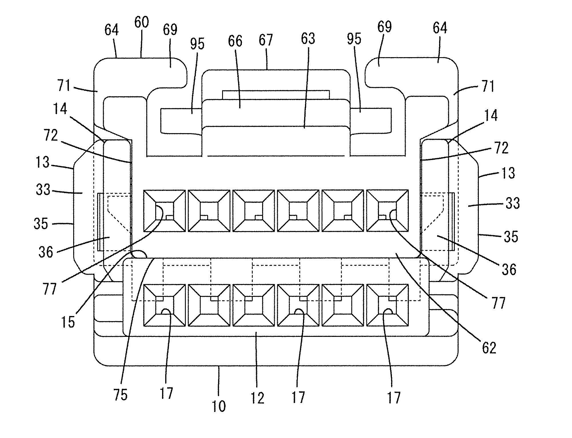
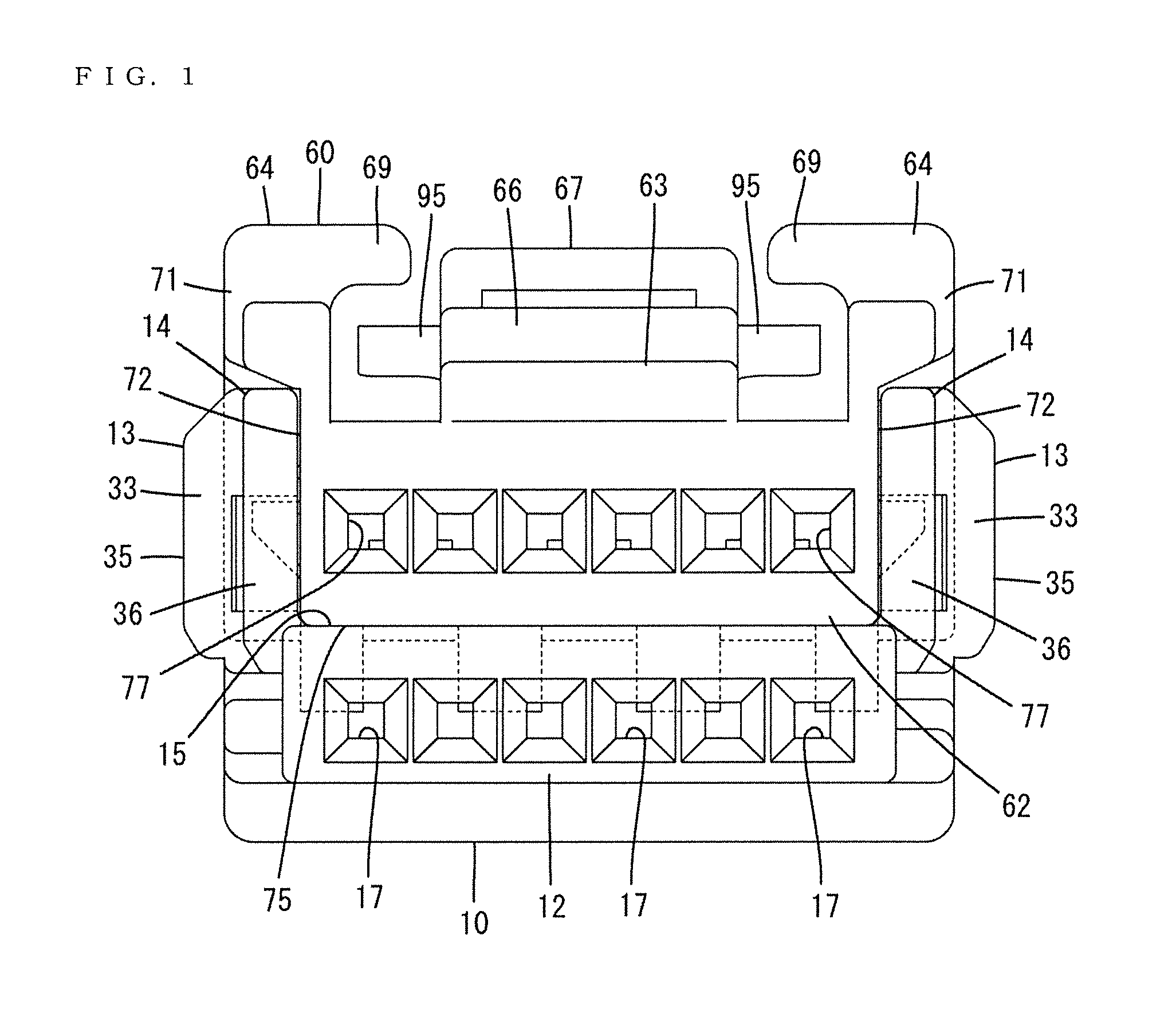
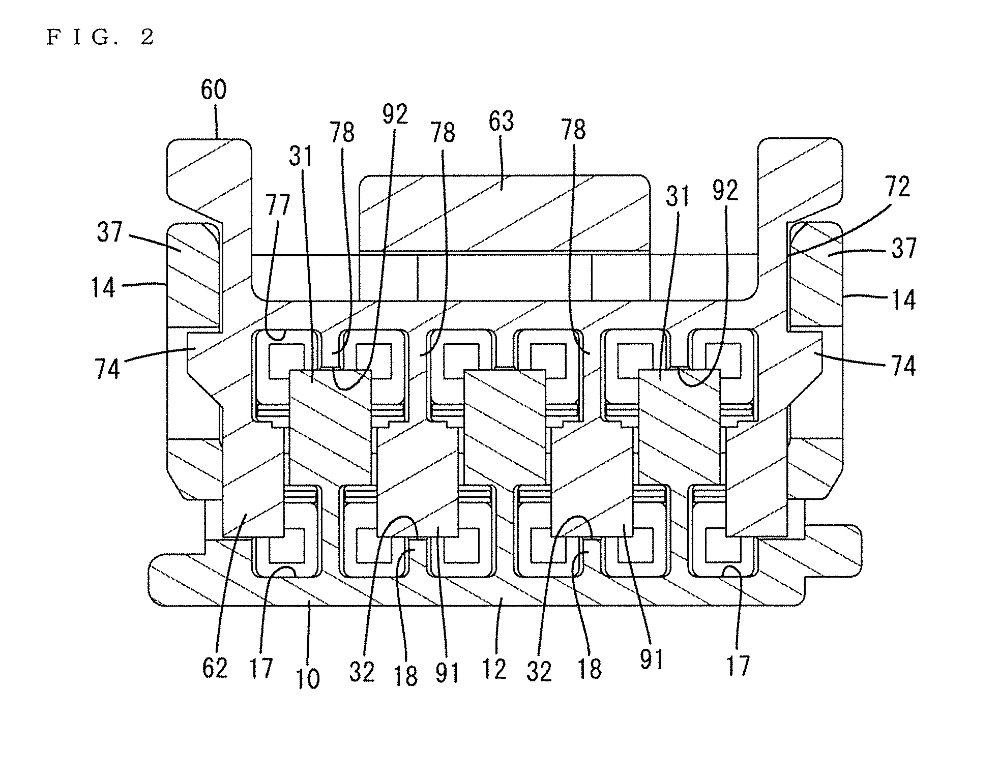
[0027]A connector in accordance with an embodiment is described with reference to FIGS. 1 to 14. The connector of this embodiment includes first and second housings 10, 60 to be assembled in a laminated state, as shown in FIG. 5, and first and second terminal fittings 11, 61 to be accommodated respectively into the first and second housings 10, 60. As shown in FIG. 4, the first and second housings 10, 60 that have been assembled with one another are connectable to a mating housing 100 from the front (left side in FIG. 4).

[0028]The first and second terminal fittings 11, 61 are long and narrow in a front-back direction, as shown in FIG. 5, and are formed into the same shape by bending an electrically conductive metal plate. Rear ends of the first and second terminal fittings 11, 61 are crimped and connected to end parts of wires 110, 160. Front parts of the first and second terminal fittings 11, 61 are box-shaped, and male tabs of unillustrated mating terminal fittings are inserted th...


PUM


Abstract

A connector is miniaturized and while still preventing damage to locking lances. Deflectable first and second locking lances (19, 79) configured to lock first and second terminal fittings (11, 61) are arranged to be exposed on first and second facing surfaces (15, 75) of first and second housings (10, 60). When the first and second housings 10, 60 are assembled, the first and second locking lances (19, 79) are arranged back-to-back with each other. Surfaces of the first and second locking lances (19, 79) facing the first and second cavities (17, 77) on tip parts in a projecting direction are continuous without any step and include locking surfaces (23, 83) configured to lock the first and second terminal fittings (11, 61) on tips in the projecting direction.

Description

BACKGROUND[0001]1. Field of the Invention[0002]The invention relates to a connector.[0003]2. Description of the Related Art[0004]Japanese Unexamined Patent Publication No. H10-162888 discloses a connector with two housing units to be laminated together. Each housing unit includes a resilient locking lance for locking a terminal fitting. The locking lance is arranged so that the back surface of the locking lance is exposed on an outer surface of the housing unit. When the two housing units are laminated together, the locking lances exposed on the outer surfaces of the housing units are held in back-to-back contact with each other to restrain mutual resilient displacements thereby firmly retaining a locked state of the terminal fittings.[0005]The locking lance is cantilevered forward in an inserting direction of the terminal fitting, and a projection for locking the connection terminal is provided is arranged behind the tip of the locking lance in the projecting direction.[0006]A rece...

Claims


Application Information

Patent Timeline
Patent Type & Authority Applications(United States)
IPC IPC(8): H01R13/424H01R13/504
CPCH01R13/504H01R13/424H01R13/4223H01R13/506H01R13/514
Inventor CHIKUSA, TAKAHIROIIHOSHI, SHINJI
Owner SUMITOMO WIRING SYST LTD
Why Eureka
Try Eureka