Air cleaner device in vehicle

a technology for air cleaners and vehicles, applied in machines/engines, combustion-air/fuel-air treatment, transportation and packaging, etc., can solve problems such as difficulty in introducing water into the air cleaner body

Inactive Publication Date: 2007-01-30
HONDA MOTOR CO LTD
View PDF6 Cites 71 Cited by
  • Summary
  • Abstract
  • Description
  • Claims
  • Application Information

AI Technical Summary

Benefits of technology

[0013]It is an object of the present invention to make water difficult to enter the interior of a body of an air cleaner device in a vehicle even when the air cleaner body is covered with water, and to make the air cleaner body difficult to be influenced by heat, and further make it difficult for dust to enter the interior of the air cleaner body.
[0016]According to the first aspect of the present invention, since a snorkel is provided in an air cleaner body in a vehicle provided with right and left seats, for example even if the air cleaner body is disposed at a position lower than the seats, it is possible to minimize the influence of water-covering. Besides, even when the air cleaner body is covered with water, the water is difficult to enter a front-end opening of the snorkel and thus it is possible to make the entry of water into the air cleaner body difficult. Moreover, the front end of the snorkel is opened between the right and left seats, so when the vehicle runs in a deep water level, a driver can easily grasp the degree of water-covering in the snorkel opening and can take a countermeasure while checking the opening at a close distance. Thus, the reliability of the vehicle when running in a river, a marsh or the like can be improved.
[0017]Further, since air is introduced through the snorkel which opens between the right and left seats where there is little dust rolled up by the rear wheels, it is possible to minimize the entry of dust into the air cleaner body.
[0018]According to the second aspect of the present invention, since the air cleaner body is disposed between the right and left side frames and spacedly from the muffler by being inclined relative to the vehicular longitudinal direction, the distance between the air cleaner body and the exhaust pipe and the distance between the air cleaner body and the muffler can be made larger and hence the air cleaner body can be made difficult to be influenced by heat from the exhaust pipe and the muffler. Consequently, it is possible to simplify or omit an anti-heat member for the air cleaner and thereby attain the reduction of cost.

Problems solved by technology

Besides, even when the air cleaner body is covered with water, the water is difficult to enter a front-end opening of the snorkel and thus it is possible to make the entry of water into the air cleaner body difficult.

Method used


Image

  • Air cleaner device in vehicle
  • Air cleaner device in vehicle
  • Air cleaner device in vehicle

Examples


Embodiment Construction

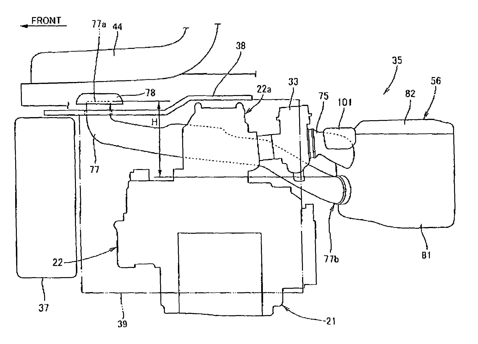
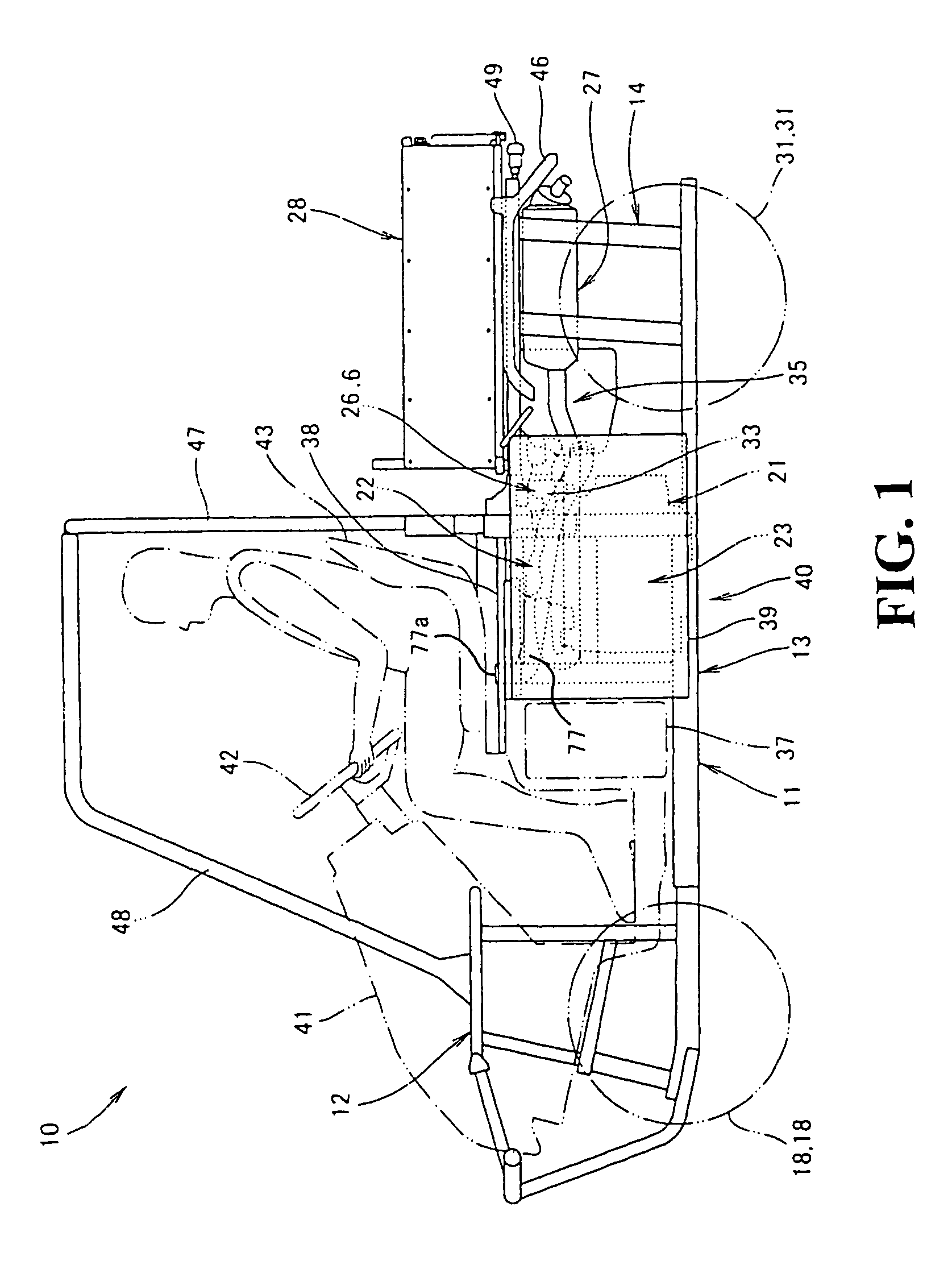
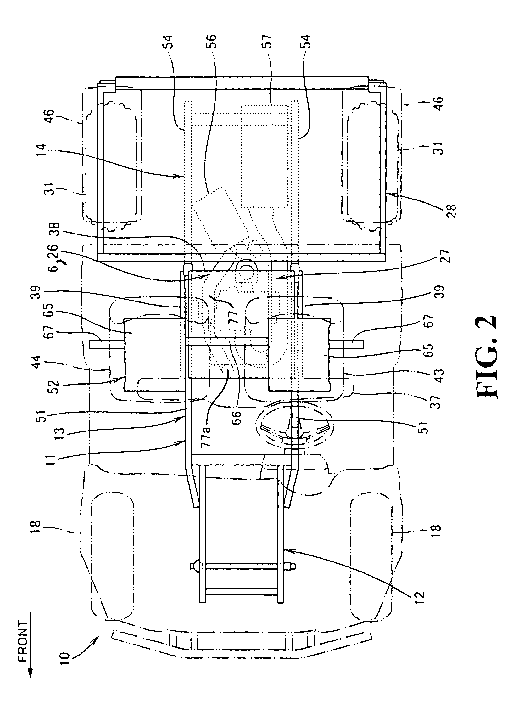
[0027]FIG. 1 is a side view of a two seater four wheel drive vehicle provided with an air cleaner device embodying the present invention, in which the vehicle 10 includes a body frame 11 (including a front frame 12, a center frame 13 and a rear frame 14), right and left front wheels 18, a power unit 21 (including an engine 22 and a transmission 23) mounted to the center frame 13, an intake unit 26 disposed behind the engine 22 to feed air and fuel to the engine, an exhaust unit 27 extending backward from a front portion of the engine 22, a cargo bed 28 secured to an upper portion of the rear frame 14 tiltably, and right and left rear wheels 31.

[0028]The intake unit 26 includes a carburetor 33 connected to the engine 22 and an air cleaner device 35 connected to the carburetor 33.

[0029]FIG. 1 also shows a fuel tank 37, an upper partition wall 38 for partitioning the power unit 21 and a passenger room from each other, a pair of right and left side partition walls 39 (only this-side one...


PUM


Abstract

An air cleaner device for a vehicle is provided with an air cleaner body containing an air cleaner element and a snorkel connected to the air cleaner body to introduce the outside air into the air cleaner body. The snorkel extends forward of the vehicle past a side of a cylinder portion which projects upward from an engine, and a front end of the snorkel opens between right and left seats of the vehicle. With this configuration, even if the air cleaner body of the air cleaner device should be flooded, it is difficult for water to enter into the interior. Further, it is difficult for the air cleaner body to be influenced by heat, and difficult for dust to get into the air cleaner body.

Description

CROSS-REFERENCE TO RELATED APPLICATION[0001]The present application claims priority under 35 U.S.C. §119 to Japanese Patent Application No. 2004-284668, filed Sep. 29, 2004, the entire contents of which are hereby incorporated by reference.BACKGROUND OF THE INVENTION[0002]1. Field of the Invention[0003]The present invention relates to an air cleaner device in a vehicle.[0004]2. Description of Background Art[0005]As a conventional vehicular air cleaner device, an air cleaner disposed in a rear portion of a vehicle body is known (see, for example, Japanese Patent Laid-Open No. Sho 61-295128).[0006]The following description is now provided about FIGS. 1, 3 and 4 in Japanese Patent Laid-Open No. Sho 61-295128.[0007]In FIG. 4, a small-sized vehicle 1 is provided with a pair of right and left side tubes 2a which constitute a body frame 2, and an engine body 22 and an air cleaner 20 are disposed between the side tubes 2a. Numeral 3 denotes a seat disposed in front of the engine body 22 and...

Claims


Application Information

Patent Timeline
Patent Type & Authority Patents(United States)
IPC IPC(8): B60K13/06
CPCB60K13/02B60K13/04F01N13/08F02M35/162F02M35/024F02M35/04F01N2340/04
Inventor NOZAKI, NAOKIINOUE, MASAHIRO
Owner HONDA MOTOR CO LTD
Why Eureka
Try Eureka