Hard surface cleaner

a technology of fluid cleaning and hard surface, which is applied in the direction of vacuum cleaners, carpet cleaners, domestic applications, etc., can solve the problems of wet floor surface, inability to extract all of the fluid, damage to the floor surface,

Inactive Publication Date: 2009-10-22
RICHARDS EDWARD
View PDF59 Cites 13 Cited by
  • Summary
  • Abstract
  • Description
  • Claims
  • Application Information

AI Technical Summary

Benefits of technology

[0006]The present invention is a portable and self-contained high-pressure fluid cleaning apparatus for use on a variety of surface floor coverings and in particular, on indoor and outdoor hard surface floor coverings that contain grooves and crevices that are ordinarily difficult to clean, such as tile, grout, epoxy and stained concrete. The apparatus operates simultaneously as both a fluid pressure cleaning device and as a wet-dry vacuum such that dirt and debris is effectively dislodged from the floor surface and is simultaneously picked up along with the ejected cleaning fluid by the vacuum suction of the apparatus. Through the use of one or more cartridge-type filter elements, the dirty cleaning fluid that is removed from the floor surface can be recycled and reused thereafter such that only one fluid tank is needed for both operations of the apparatus.

Problems solved by technology

However, a number of these systems require maintaining two separate tanks within the device such that a first tank contains the unused cleaning fluid and a second tank contains the recovered fluid and dirt that was extracted from the floor surface.
However, these types of harsh chemicals, solutions and tools having abrasive surfaces can cause damage to the floor surface.
Furthermore, many of the existing cleaning systems that use a cleaning fluid extractor method leave behind a wet floor surface as it is impossible to be able to extract all of the fluid that was distributed along the floor surface when using a suction source.
This results in a dangerous and slippery condition and requires additional time for drying before the floor surface is ready to be used.

Method used


Image

  • Hard surface cleaner
  • Hard surface cleaner
  • Hard surface cleaner

Examples


Embodiment Construction

[0026]For a better understanding of the present invention, reference may be had to the following detailed description taken in conjunction with the appended claims and the accompanying drawings.

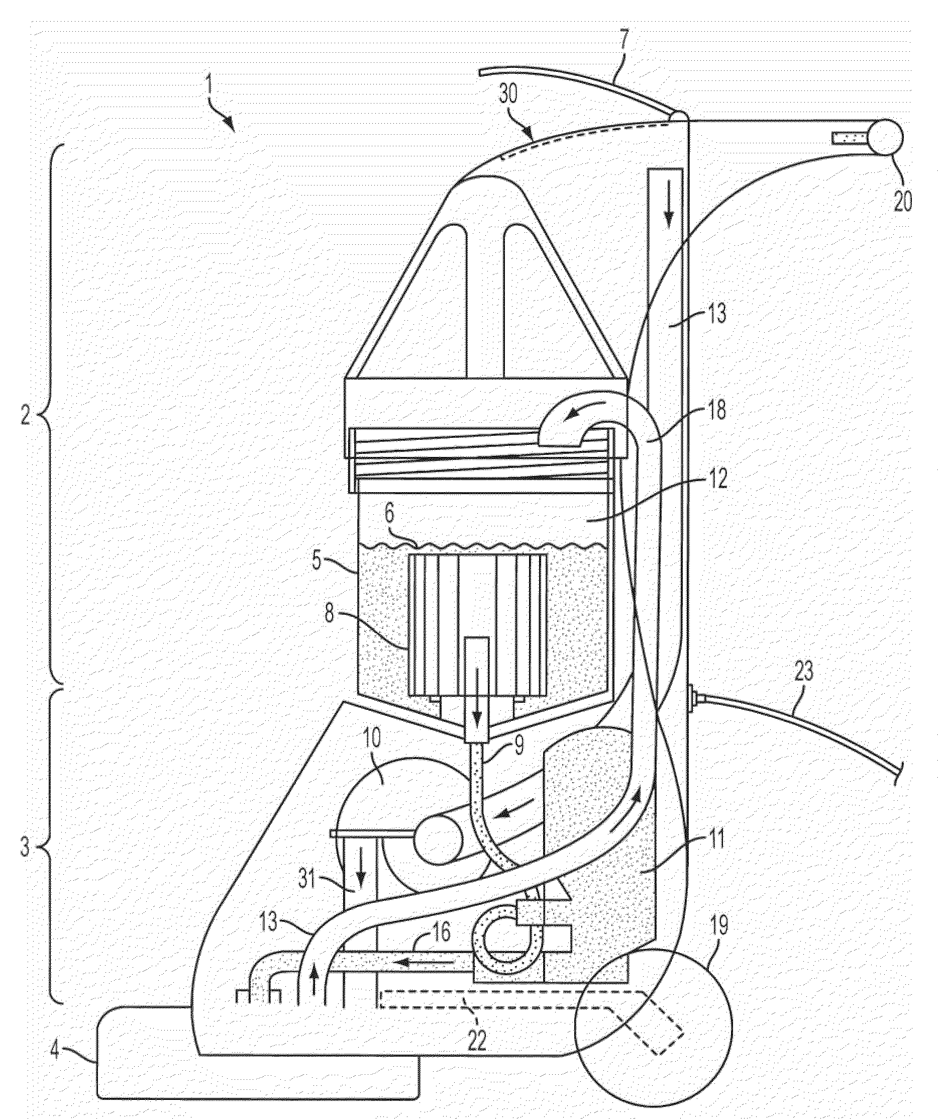
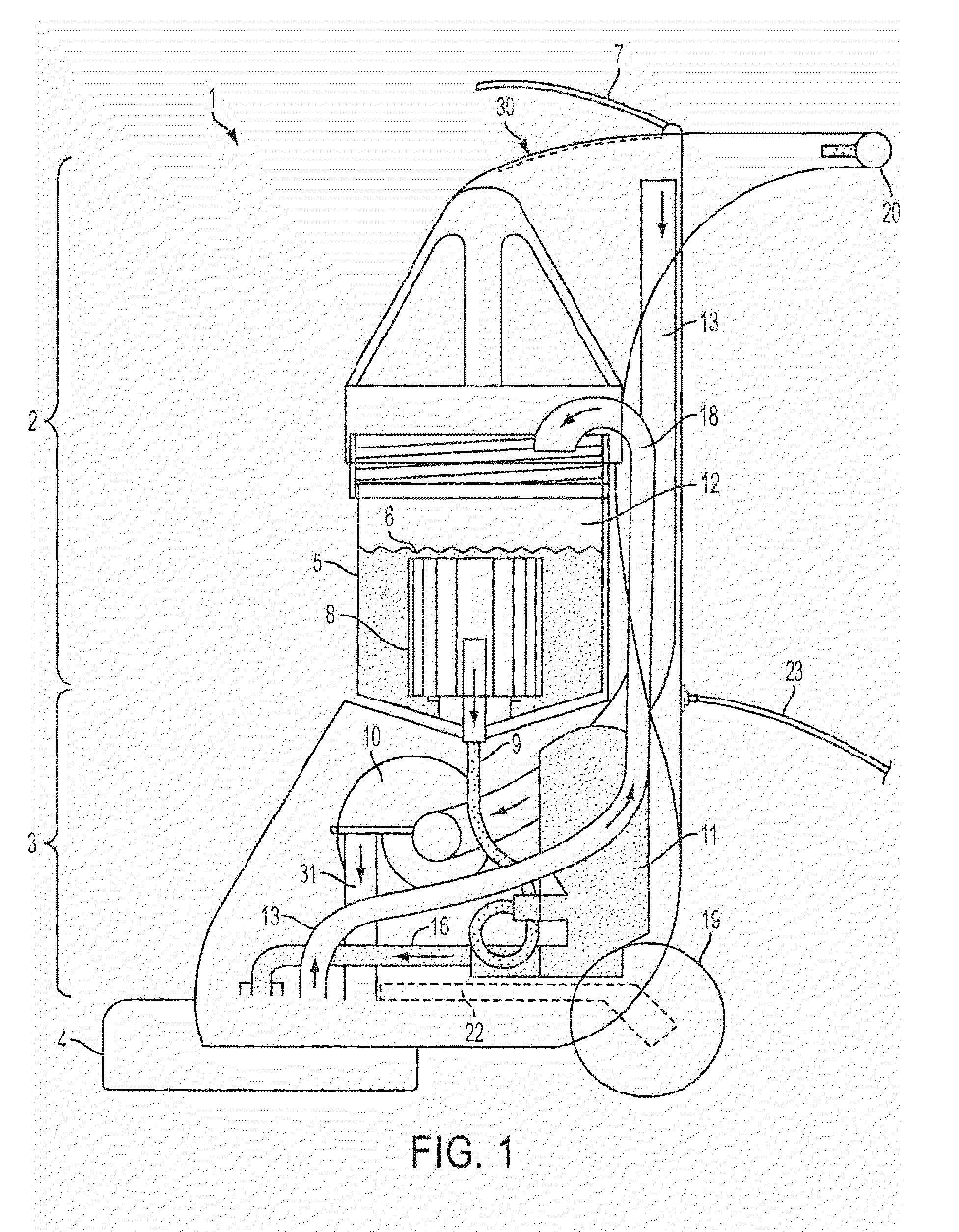
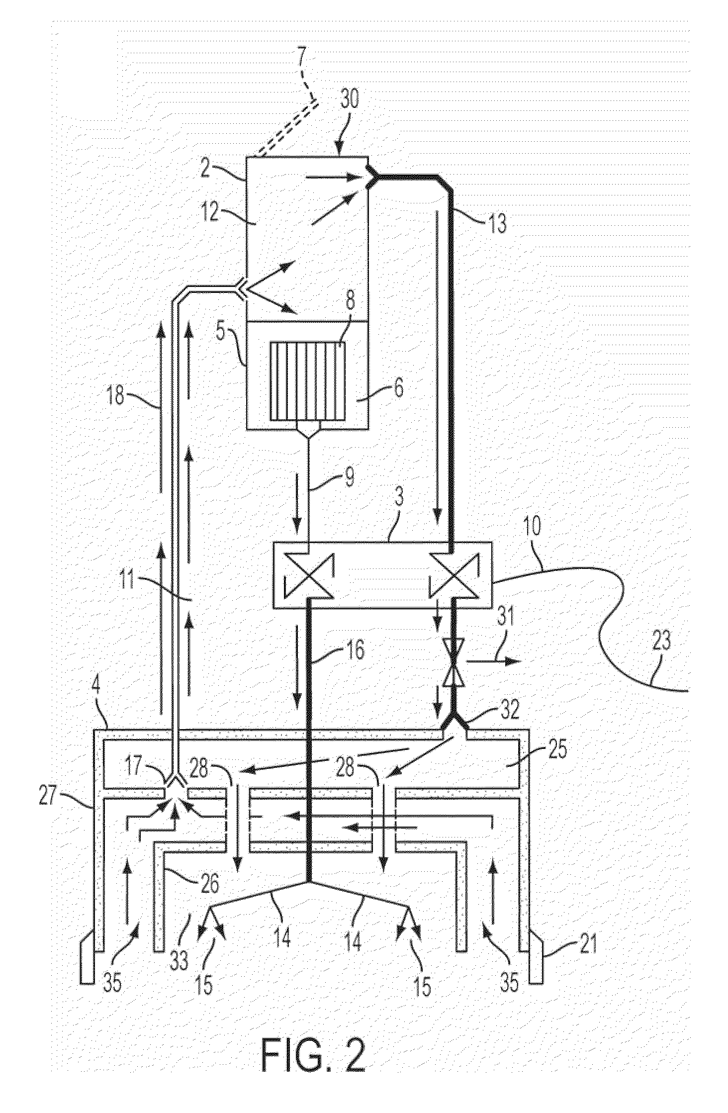
[0027]The present invention is a portable, self-contained hard surface floor cleaning apparatus 1 that operates simultaneously as a water pressure cleaning device and a wet-dry vacuum. The apparatus is suitable for use in both indoor and outdoor spaces on a variety of hard surface floor coverings such as tile, grout, epoxy and stained concrete. The apparatus is comprised of a tank portion 2, a power portion 3 and a cleaning head portion 4 that may optionally be detachable.

[0028]FIG. 1 depicts an embodiment of the present invention. The tank portion 2 is comprised of a tank 5 that is preferably positioned upright above the power portion 3 wherein the tank's volume is partially filled with a suitable cleaning fluid 6 that is fed through a supply line 9 to the power portion 3 of the apparatus. B...


PUM


Abstract

A surface cleaner, comprising a tank having a fluid-filled part and an air-filled part; a vacuum pump; a fluid pressure pump; a cleaning head having a cleaning chamber and a vacuum chamber, the cleaning chamber forming a cavity bounded by a surface to be cleaned, the vacuum chamber having an inlet lip at the periphery of the cleaning chamber; jet nozzles mounted within the cleaning chamber; wherein the pressure pump draws fluid from the tank and ejects it into the cleaning chamber through the nozzles; wherein the vacuum pump maintains a low pressure in the air-filled part of the tank and a high pressure in the cleaning chamber; and wherein the inlet lip is in fluid communication with the air-filled part of the tank portion whereby fluid ejected into the cleaning chamber is drawn into the inlet lip and returned to the tank.

Description

PRIORITY CLAIM[0001]This application claims priority to and the benefit of the filing date of corresponding U.S. Provisional Application Ser. No. 61 / 046,621, filed on Apr. 21, 2008, the disclosure and contents of which are expressly incorporated herein by reference.FIELD OF INVENTION[0002]The present invention relates to high-pressured fluid cleaning systems for cleaning indoor and outdoor floor surfaces.BACKGROUND OF THE INVENTION[0003]Several existing cleaning systems use an extractor method wherein a detergent cleaning fluid is distributed by the device along the floor surface and the device simultaneously extracts the fluid and the dirt from the floor surface using a suction source in a continuous operation as the device moves along the surface. However, a number of these systems require maintaining two separate tanks within the device such that a first tank contains the unused cleaning fluid and a second tank contains the recovered fluid and dirt that was extracted from the flo...

Claims


Application Information

Patent Timeline
Patent Type & Authority Applications(United States)
IPC IPC(8): A47L7/00
CPCA47L11/34A47L11/4083A47L11/4044
Inventor RICHARDS, EDWARD
Owner RICHARDS EDWARD
Why Eureka
Try Eureka