
Culinary utensil

a technology for utensils and utensils, which is applied in the field of utensils, can solve the problems of difficult cleaning, inability to maintain, and inability to use plastic or wooden utensils,

Inactive Publication Date: 2006-11-16
MAXPAT TRADING & MARKETING FAR EAST LTD
View PDF7 Cites 14 Cited by
  • Summary
  • Abstract
  • Description
  • Claims
  • Application Information

AI Technical Summary

Benefits of technology

"The present invention provides a culinary spatula with a main body made of stainless steel and a front end covered with a heat-resistant soft plastic material. The soft plastic material is attached to the front end of the spatula and integrally forms the utility portion of the spatula. The spatula is particularly useful with non-stick cooking vessels. The main body is made of stainless steel, which is durable and can protect the non-stick surface of the cooking vessel. The handle is elongate and perpendicular to the front end of the utility portion. The front end is slanted for better engagement with foodstuffs or the surface of a cooking vessel. The material used for the soft plastic material is heat-resistant and safe with food contact. The spatula may have one or more openings at the front end for easy attachment of the soft plastic material. The spatula may also have further means for enhancing fixed attachment of the soft plastic material, such as notches on the front end. The soft plastic material may cover the front end of the spatula and have a thinner outer portion to engage, contact, or stir foodstuffs in a cooking vessel."

Problems solved by technology

Yet, such plastic or wooden spatulas are not durable and more difficult to clean and the use thereof is often not desirable.

Method used


Image

  • Culinary utensil
  • Culinary utensil
  • Culinary utensil

Examples


first embodiment

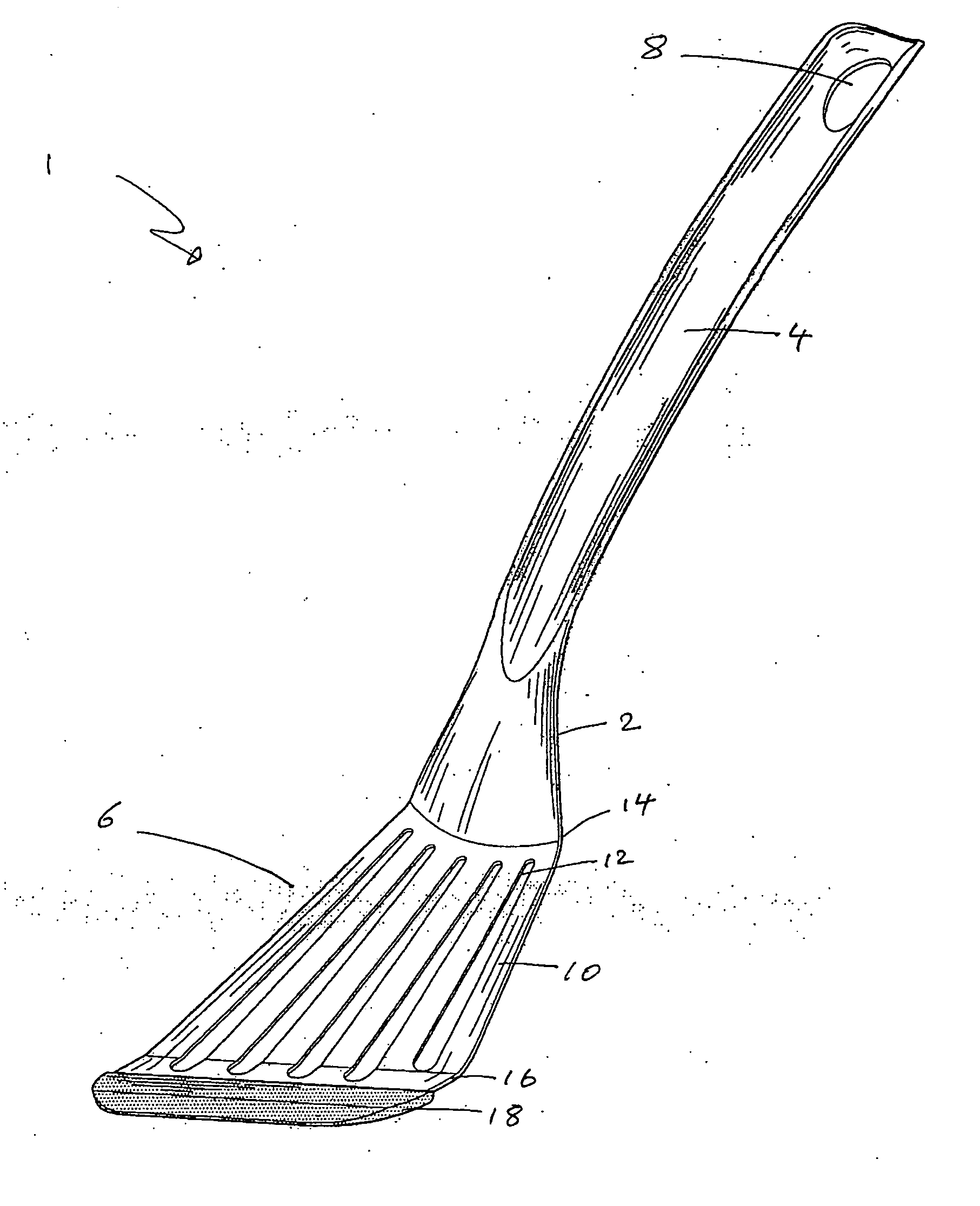
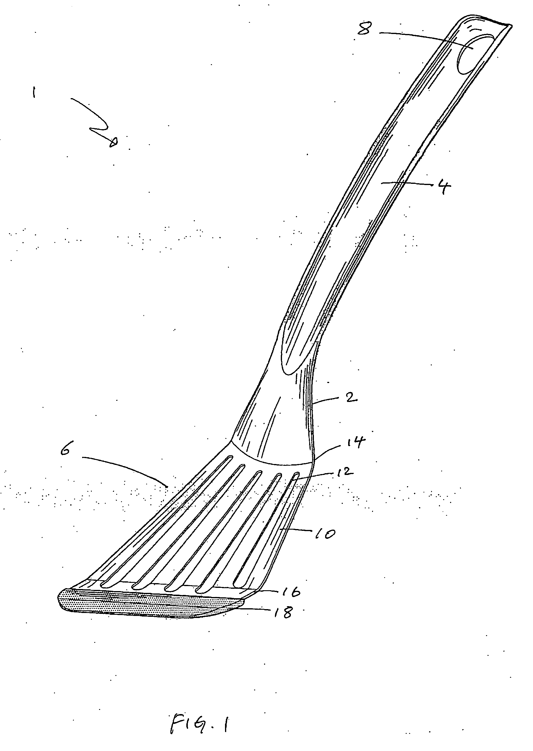
[0023] Turing to the figures, FIGS. 1 to 2 shows a culinary utensil in the form of a spatula according to the present invention. The spatula, generally designated 1, comprises a durable and metallic main body 2 including an elongate handle portion 4 and a utility portion 6. The handle portion 1 is provided with an opening 8 such that the spatula 1 may be secured to a hook for storage in a kitchen.

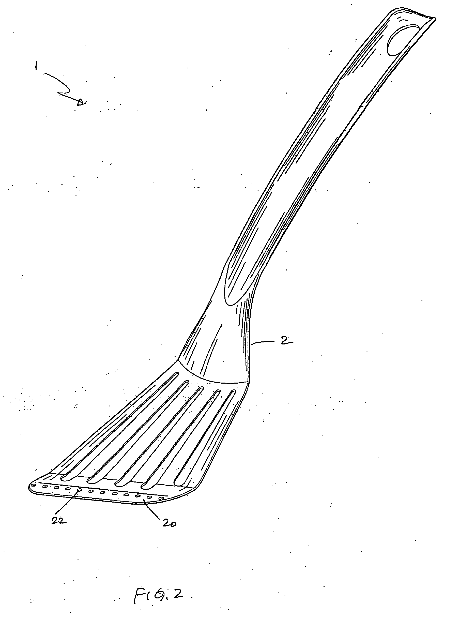
[0024] The utility portion 6 comprises a generally flat member 10 provided with a number of slits 12 arranged roughly parallel to each other. The flat member 10 has a narrower rear region 14 connecting to the handle portion 4 and a wider front region 16. The front region 16 is provided with an elongate and relatively thin strip 18 made of a heat resistant silicone material. The strip 18 is relatively soft and non-scratching to non-stick surfaces of cooking vessels. FIG. 2 shows the main body 2 of the spatula 1 of FIG. 1 but without the strip 18. The utility portion 6 of the main body 2 is p...

second embodiment

[0025] FIGS. 3 to 5c illustrate a culinary utensil, generally designated 30, according to the present invention. The spoon 30 is generally similar to the spatula 1 of the FIG. 1 in terms of its overall construction. The utensil 30 comprises a main body 32 including a handle34 and a utility portion 36, and the utility portion 36 resembles a spoon shape structure. The utility portion 36 likewise is provided with a front region 38 to which a similar soft strip 40 is attached thereto. The soft strip 40 is made of a heat resistance silicone. As shown in FIG. 4, at a front end 42 of the main body 32 is provided with two elongate openings 44, 46 over which an upper portion 48 and a lower portion 50 the strip 40 covers (see FIG. 5c). It is envisaged that during manufacturing, the strip 40 once attached to the front end 42 of the main body 32 is subject to sufficiently high pressure and / or temperature such that it is permanently sealed at the area with the openings 44, 46.

[0026]FIGS. 5b to 5...


PUM


Abstract

A culinary spatula comprising a main body including a handle portion and a utility portion having a front end covered with an elongate member made of a heat resistant soft plastic material, and across the front end wherein the member sandwiches and / or is fixedly attached to the front end such that the member and the front end together integrally form the utility portion of the spatula.

Description

FIELD OF THE INVENTION [0001] This invention relates to culinary utensils for mixing or stirring foodstuffs in a cooking vessel and particularly culinary spatulas or culinary spoons or the like. BACKGROUND OF THE INVENTION [0002] Non-stick cooking vessels such as non-stick pans and pots have become very popular in the last two decades. The cooking surface of these utensils is normally covered with one or more layers of a non-stick material or Teflon™ or Teflon™-like substance. One common flaw with these vessels is that the non-stick surface tends to deteriorate rather rapidly such that they often become no longer non-stick after a short period of time. While non-stick vessels are desirable in that it is easy to use and easy to clean, their durability is often poor. [0003] The present invention is directed to overcoming the problems associated with such cooking vessels, or at least to provide a useful alternative to the public. SUMMARY OF THE INVENTION [0004] According to the present...

Claims


Application Information

Patent Timeline
Patent Type & Authority Applications(United States)
IPC IPC(8): A47J43/28
CPCA47J43/288
Inventor YU, SIU KWAN
Owner MAXPAT TRADING & MARKETING FAR EAST LTD
Learn More