Optical properties restoration apparatus, the restoration method, and an optical system used in the apparatus

a technology of optical properties and restoration methods, applied in the field of optical properties restoration apparatuses and restoration methods, and the restoration method of optical systems used in the apparatus, can solve the problems of difficult to avoid the emission of organic gases inside the vacuum zone, the appearance of the adsorption phenomenon itself is unavoidable, and the degradation of optical properties outside the light transmitting

Inactive Publication Date: 2005-11-03
MITSUBISHI HEAVY IND LTD
View PDF1 Cites 14 Cited by
  • Summary
  • Abstract
  • Description
  • Claims
  • Application Information

AI Technical Summary

Problems solved by technology

Problems in the Degradation of Optical Properties Outside of the Light Transmitting Window
However, in actual practice, it is difficult to avoid the emission of organic gases inside vacuum zone 14, which can arise from various factors such as lubricating oil that is used for the mechanical drive structure, contamination of the work sample, out gassing from the O-rings, out gassing from plastic parts, inadequate degreasing or cleaning of the parts, or contamination introduced by human error.
This adsorption probability varies according to the material comprising the light transmitting window 8 and the type of organic gases, but the appearance of the adsorption phenomena itself is unavoidable.
The problem is one of diminishing transmission through the light transmitting window 8 over a long period of time.
In spectrographic applications, when the quantity of light from the light source diminishes, it creates drift which affects the accuracy of the measurements, and in applications involving surface treatments by ultraviolet light irradiation, problems arise due to inadequate processing caused by diminished irradiation intensity.
One means of addressing this problem of the carbon buildup phenomenon is to strive for an oil-free vacuum zone 14, however, once an organic substance has contaminated vacuum zone 14, the cleanup process is extremely difficult.
This operation required several hours time during which the lamp could not be used.
However, as described above for vacuum zone 14, if the apparatus involved was one that required repeatedly opening to the atmosphere or vacuum release (such as in a spectrographic application where samples have to be replaced, in applications where optic elements have to be adjusted, or where work pieces need to be exchanged during surface treatments, etc.), even if the spec calls for no organic contamination to be introduced during the assembly and adjustment processes, not introducing such contamination is rare in actual practice and hence, it would be impossible to avoid degradation of light transmitting window 8
Not only does this disclosure have an objective that differs from removing accumulated carbon films from surfaces, but it further does not resolve the problem of cleaning optical elements such as the light transmitting window when there is a need to break the vacuum.
As a result, the method can only be used in an environment of near normal atmospheric pressure—it cannot perform optical element cleansing of light transmitting windows and the like under vacuum conditions, and it does nothing to resolve the problems that develop when it is necessary to break the vacuum.
This phenomenon is unavoidable so long as the conditions of the presence of organic gases and ultraviolet light, especially vacuum ultraviolet light, coexist.
Hereinafter, any of such objects will be referred to collectively as “optical elements.” When carbon accumulates on these optical elements it causes serious problems by reducing their light transmission and light reflectivity.
Formerly, to counter such diminishment of the light transmission and reflection, such optical elements had to be replaced with new ones, but this approach leads to high maintenance costs and keeps the apparatus out of service for the time required for maintenance.
Problems in the Degradation of Optical Properties Inside of the Optical Systems
The problem of lowing the light transmitting property from short wavelength ultraviolet light is not limited to the degradation of optical properties outside of the light transmitting window, but also the degradation of optical properties inside of the light transmitting window.
Further, a problem with mercury vapor lamps is more serious comparing to the previous time, that the quartz glass used in them loses its clarity.
So doing would impede the crystallization (losing the clarity) of the arc tube even after it had been operating for long periods of time, and thereby impede the decline in light flux (illumination sustenance rate) to make it possible to maintain bright pictures and high quality displays over a long period of time for projection type displays.
However, this prior art technology related to quartz glass, especially to that used in low pressure mercury discharge lamps, and it regulated the thickness of the protective film where the mercury atoms existed as a means to deal with the problem of the mercury being deposited upon the inside wall of the arc tube to thereby lower the transmission rate of light through the quartz glass and cause the blackening of the discharge lamp, which further diminishes its irradiation efficiency.
Furthermore, with very short wavelengths of vacuum ultraviolet light in the 150 nm vicinity such as used with high energy fluorine lasers, not only does the foregoing light transmission rate decline, but the material cannot stand up to the application and the losing the clarity occurs.
However, using fluorine compounds to dope the silica glass base stock only allows about a 50% transmission range in the 160-190 nm wavelength ranges, and it cannot stand up to use in the lower wavelengths of vacuum ultraviolet light.
However, there has been no disclosure of any report that dealt with countermeasures of losing the clarity for MgF2.
To wit, when the magnesium fluoride is used as the material for light transmitting windows, such windows exhibit a poorer longevity than other window materials, and compared with lamps that use other window materials, lamp longevity itself is only about half or less.
There have been no proposals for practical technology that was effective in preventing the diminishment of the light transmission rate through MgF2, which is the material used in light transmitting windows for the 122 nm wavelength vacuum ultraviolet light generated by microwave-excited hydrogen ultraviolet lamps.
The replacement of light transmitting window 8 requires the breaking of the lamp's vacuum and several hours of labor, during which time, the lamp cannot be used.
Thus, it is difficult to use such lamps in applications that require long-term monitoring, such as employed in environmental measurements.

Method used


Image

  • Optical properties restoration apparatus, the restoration method, and an optical system used in the apparatus
  • Optical properties restoration apparatus, the restoration method, and an optical system used in the apparatus
  • Optical properties restoration apparatus, the restoration method, and an optical system used in the apparatus

Examples


first preferred embodiment

[0128] The first Preferred embodiment implementations for the present invention in suppressing or removing carbon adherents from outer surface 11 of light transmitting window 8 shall be described in the Examples below with reference to the figures. In addition, preferred embodiments for suppressing or removing carbon adherences from optical systems located in vacuum zone 14 will be explained as well with reference to the figures.

[0129] The present invention is not confined to these embodiment examples, and it may also be effectively applied to lamps or laser apparatus that produce light by electrical discharge or by heating.

example 1

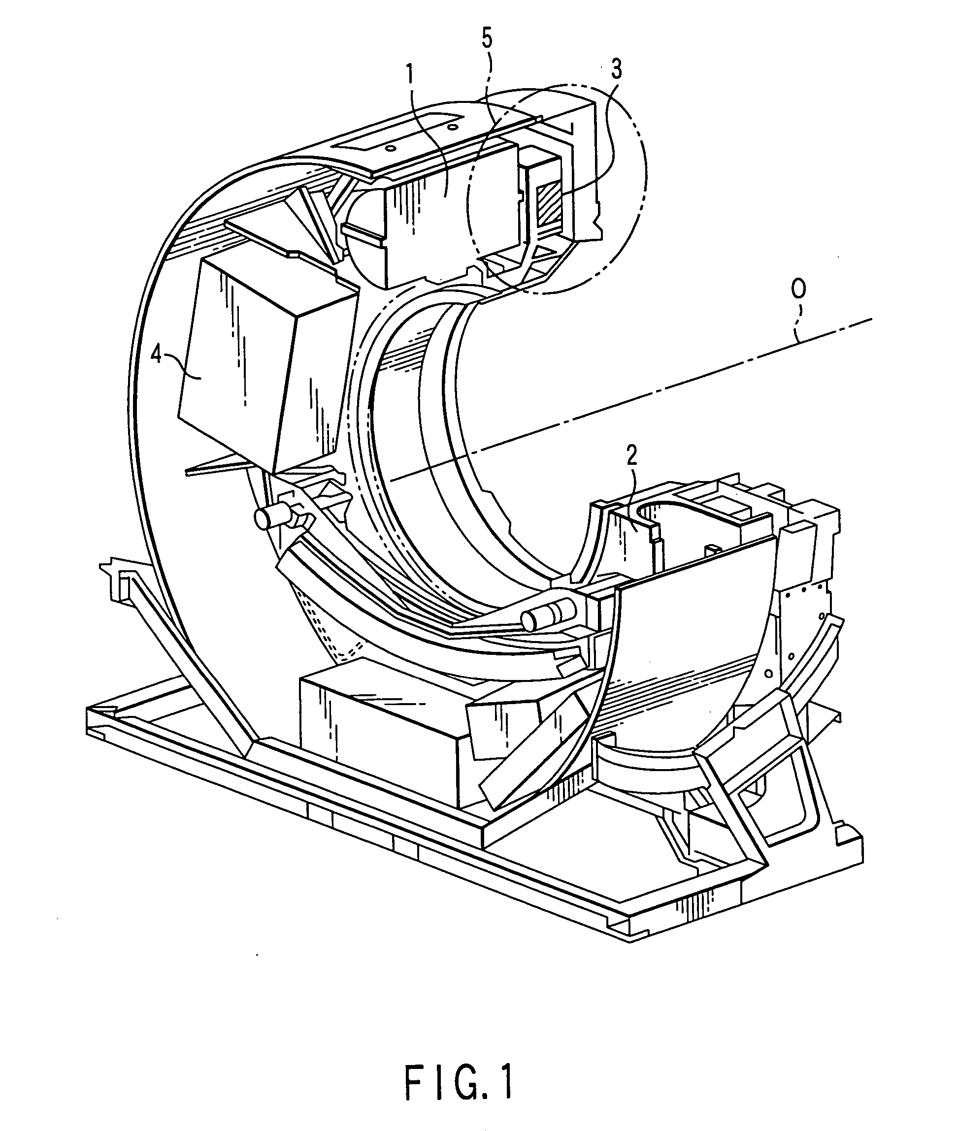
[0130]FIG. 1 is a diagram used to explain the structure of the microwave-excited hydrogen ultraviolet lamp used in the first example of the first preferred embodiment according to the present invention.

[0131] The retaining member (flange) 17 where light transmitting window 8 is attached is disc shaped and its center is aligned with the bore of discharge tube 1, and it contains an opening which is of a larger diameter than the inside diameter of the discharge tube. Window flange 17 includes an O-ring groove to create a seal over the opening for light transmitting window 8, and there is also a hollow lid-shaped jig 20, bolt holes to affix it, and an O-ring groove which connects to discharge tube 1 to maintain a vacuum with window flange 17.

[0132] The internal structure of jig 20 employs two-stage concentric circles and bounds the space for housing light transmitting window 8 and the space encompassed by discharge tube 1. On the end that encompasses discharge tube 1 the face has been...

example 2

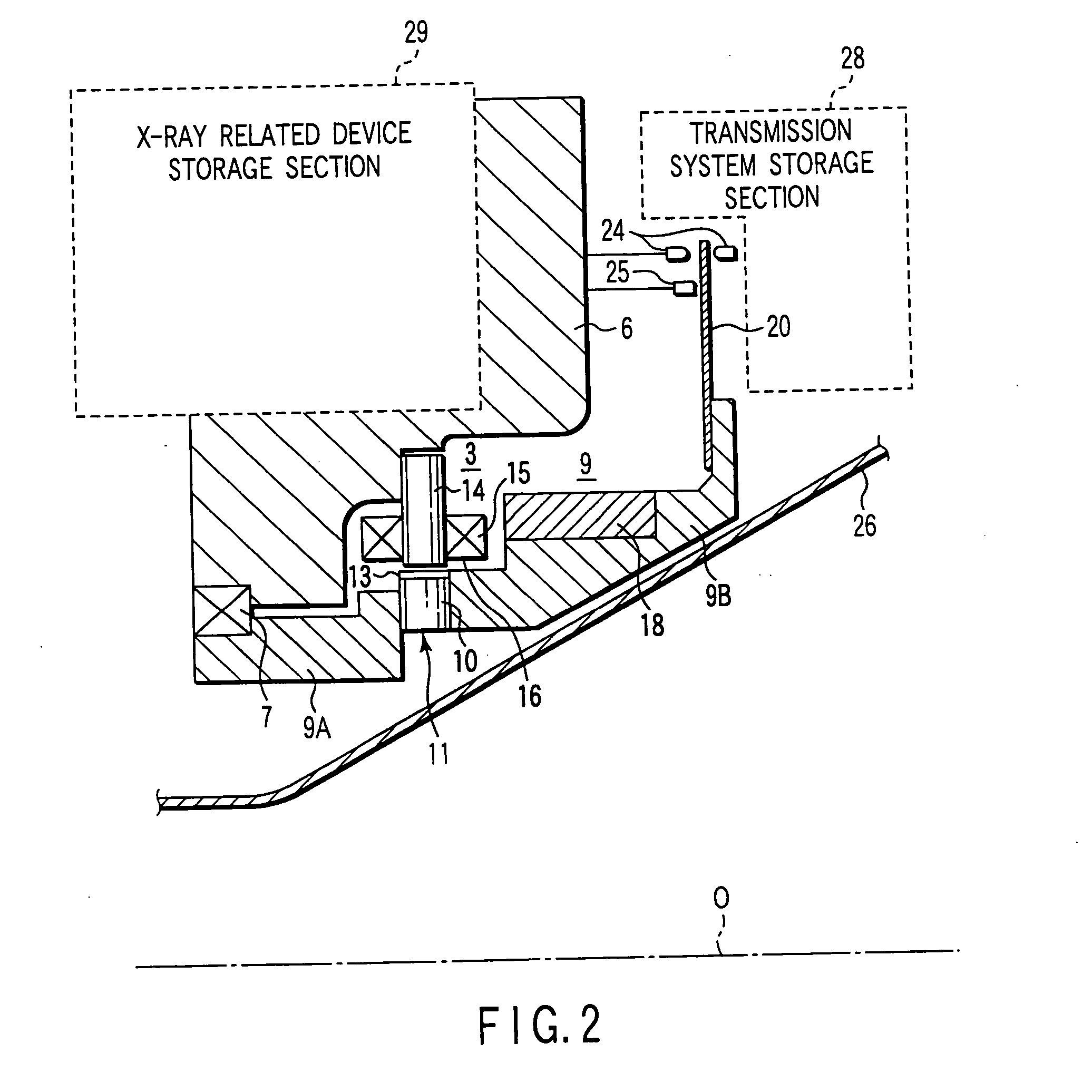
[0155]FIG. 2 is a diagram showing a microwave excited hydrogen ultraviolet lamp that will be used to describe the second example of the first preferred embodiment according to the present invention. Further elaboration of structural and operational elements that are similar to those of Example 1 will be omitted. The specifications of light transmitting window 8 were the same as those explained for Example 1. Further, a photodiode 12 was positioned to receive the light output of lamp emitted light 9 as a means of monitoring the amount of light output from said lamp.

[0156] Water vapor was supplied to vacuum zone 14 using the following method, and it was adjusted to a specific gas partial pressure. Glass tube 24 (tube diameter Φ6 mm), which was filled with 1 mL of water 25 (pure water that was distilled, ion-exchanged processed and filtered) was connected with tube 16d via flange 17. The structure of flange 17 incorporated an O-ring to seal the glass tube off from the atmosphere, and ...


PUM


Abstract

The objectives of the present invention are to prevent or inhibit the deterioration of optical systems that determine the longevity of an optical apparatus which delivers effects such as light transmission, diffraction, reflection, spectrum generation, and interference, and these combinations, and by so doing, decrease the frequency of maintenance operations such as window replacement and to reduce the costs for such operations. This invention is characterized by steps of creating a near vacuum zone with a presence of active energy to excite an oxidation reaction of carbon wherein the near vacuum zone faces the lighting surfaces of the optical system; generating negative ions or radicals in the near vacuum zone such as unstable chemical seeds containing oxygen atoms, such as OH radicals, OH ions, ozone, O2 ions, O-radicals; and removing or reducing the accumulated carbon which deposits on the lighting surface, by reacting the deposited carbon with the negative ions or radicals. More specifically, the method according to this invention is characterized by the step of supplying active energy while supplying a flow of gases containing oxygen atoms such as water gas or oxidizing gas (for example, water vapor, oxygen, hydrogen peroxide, ozone or mixtures of said gases with inactive gases (including air)) into the near vacuum zone, thereby removing or reducing the accumulated carbon which deposits on the lighting surface by exciting the oxidation reaction of the accumulated carbon with the supplied active energy.

Description

BACKGROUND OF THE INVENTION [0001] 1. Field of the Invention [0002] The present invention relates to an apparatus and method for improving the reliability and longevity of optical properties of an optical system by preventing, suppressing, or improving degradation of optical properties of an optical system lying in output light or along a light path of said output light, wherein said optical system is provided within a near vacuum zone where organic components may be decomposed, said degradation is caused by carbon deposited or accumulated upon light irradiation surfaces, light reflection surfaces, light emission surfaces (collectively called ‘lighting surfaces’) of said optical system, and said surfaces faces said vacuum zone. More specifically, it relates to an optical properties restoration apparatus and a method to use it, and such optical properties restoration apparatus is used for improving the optical property of a variety of optical systems provided outside of a light trans...

Claims


Application Information

Patent Timeline
Patent Type & Authority Applications(United States)
IPC IPC(8): B08B7/00B08B17/00G02B27/00H01L29/76
CPCB08B7/0035G02B27/0006B08B17/00G02B1/14
Inventor SAKAI, SATOSHITSURUGA, SHIGENORIYAMAKOSHI, HIDEOKURIBAYASHI, SHIZUMADANNO, MINORUFUTAMI, HIROSHIYAMAZAKI, NORIKO
Owner MITSUBISHI HEAVY IND LTD
Why Eureka
Try Eureka