[0009]An
advantage of some aspects of the invention is to provide an image forming apparatus, and an image forming method, which, even using a liquid developer, can effectively carry out an image formation after a cleaning of an intermediate transfer medium while more effectively carrying out a removal of
solid toner remaining on the intermediate transfer medium after a transfer.
[0011]Consequently, even in the event that
solid toner from the liquid developer adheres to the transfer medium with an adhesion greater than an adhesion to the latent image carrier, as in the heretofore known apparatus heretofore described, it is possible to efficiently remove solid toner adhering to the latent image carrier after the transfer, and solid toner adhering to the transfer medium after the transfer, by means of biases applied to the latent image carrier cleaning roller and the transfer medium cleaning roller, respectively.
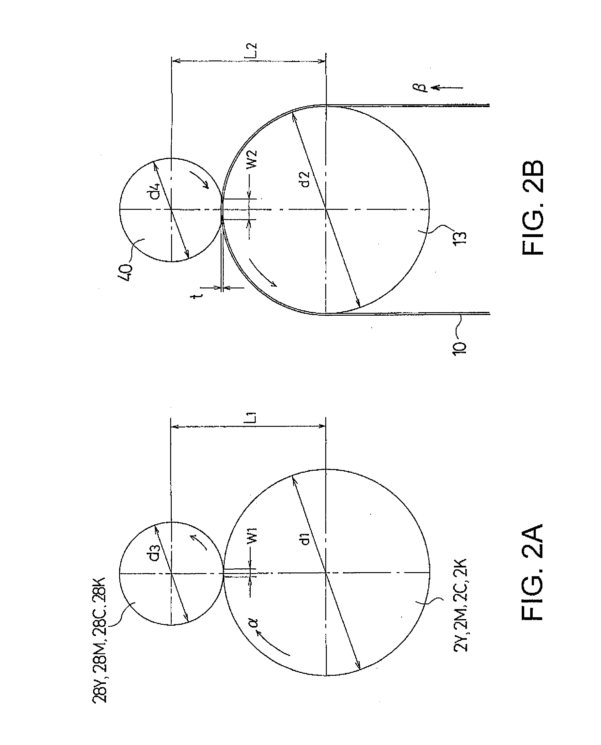
[0012]In particular, by means of the fact that the second nip width of the transfer medium cleaning roller is larger than the first nip width of the latent image carrier cleaning roller, it is possible to set a solid toner nip
transit time (a solid toner
electrophoresis time) in the transfer medium, which has a high solid toner adhesion and is hard to clean, so as to be longer than a solid toner nip
transit time in the latent image carrier. Consequently, it is possible to effectively remove solid toner on the transfer medium which is hard to remove. Also, by this means, as it is possible to make the bias applied to the transfer medium cleaning roller comparatively low, it is possible to suppress an effect on the transfer medium due to the bias. As a result, as it is possible to suppress charge on the transfer medium, it is possible to effectively carry out an image formation after a cleaning of the transfer medium.
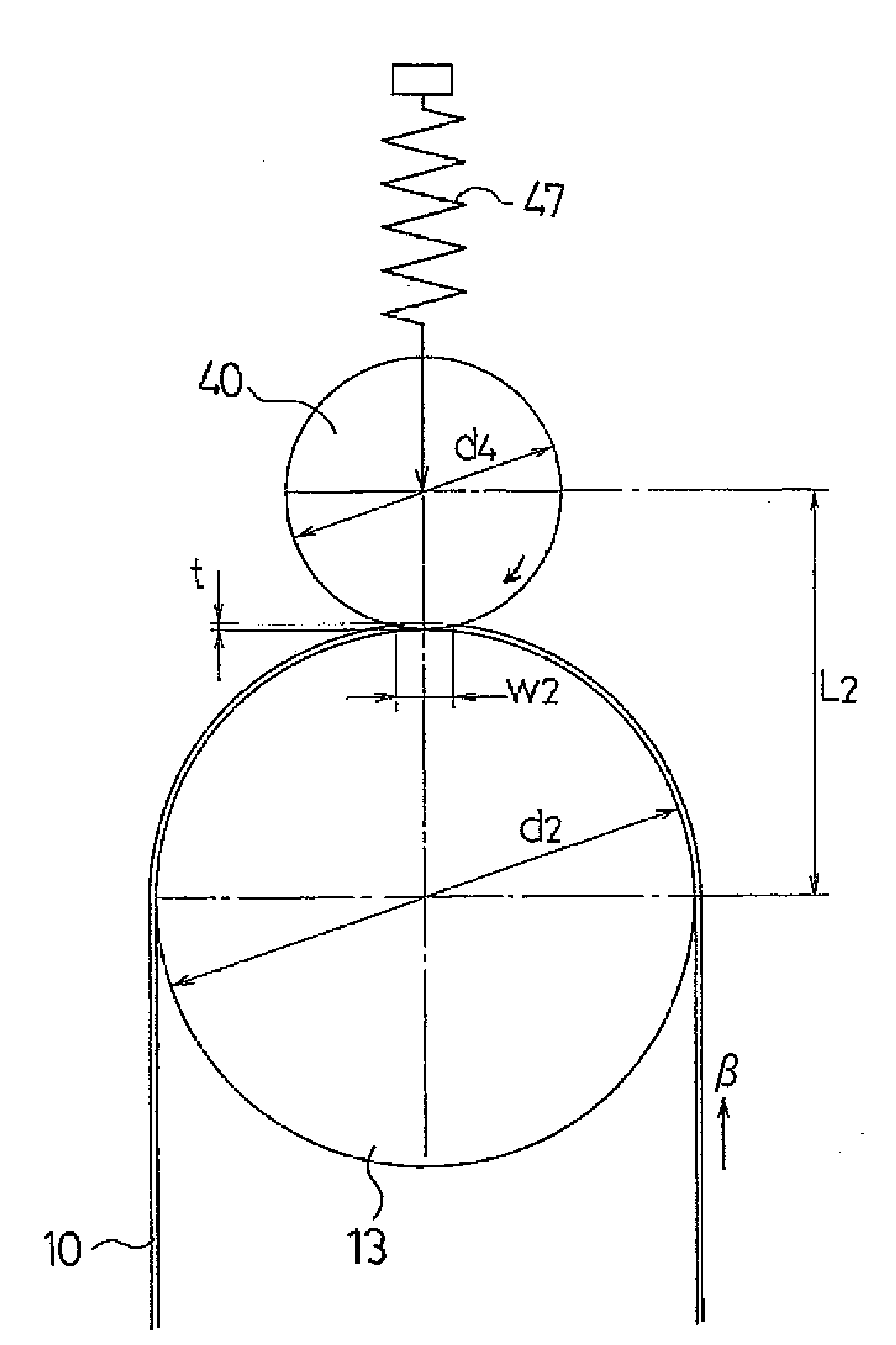
[0013]Meanwhile, the transfer medium cleaning roller, when viewed in cross-section of a central portion of a second roller in an axial direction, is disposed on a second roller side of a contact point at which an imaginary tangent line common to the second roller and a third roller makes contact with the third roller. Consequently, it is possible to set a nip width between a transfer belt cleaning roller and a transfer belt so as to be larger. As a result, as well as it being possible to reduce a transfer belt cleaning bias per unit area, it is possible to increase a time for which the transfer belt cleaning roller makes contact with the transfer belt. By this means, even in the event that the transfer belt cleaning bias is set so as to be comparatively high, it is possible to effectively clean the transfer belt while suppressing an effect on the transfer belt due to the cleaning bias.
[0014]Furthermore, as the heretofore described nip widths are made different from each other by adjusting a supporting position, a
contact pressure, or a
hardness, of each of the latent image carrier cleaning roller and the transfer medium cleaning roller, it is possible to easily carry out a setting of each nip width. Then, by the nip widths being set in such a way that the latent image carrier and the transfer medium can be cleaned at the same bias, it is possible to supply each bias by means of one and the same power supply. Consequently, as well as it being possible to reduce a number of parts, it is possible to effectively realize a
miniaturization of the apparatus.
[0015]Furthermore, a transfer medium cleaning blade is provided which, being brought into
abutment with the transfer medium, removes the liquid developer remaining on the transfer medium cleaned by the transfer medium cleaning roller. In this case, after a cleaning of solid toner from the liquid developer by the transfer medium cleaning roller, most of the liquid developer remaining on the transfer medium is liquid carrier. Consequently, as the transfer medium cleaning blade only removes the liquid carrier, it is possible to reduce a pressure at which the transfer medium cleaning blade abuts against the transfer medium. Although the transfer medium is generally softer than the latent image carrier, by the pressure at which the transfer medium cleaning blade abuts against the transfer medium being reduced, it is possible to suppress damage to the transfer medium, and achieve an increase in
life span of the transfer medium.

