Lead-free solder, and connection lead and electrical component using said lead-free solder

Inactive Publication Date: 2006-12-12
HITACHI CABLE
View PDF8 Cites 10 Cited by
  • Summary
  • Abstract
  • Description
  • Claims
  • Application Information

AI Technical Summary

Benefits of technology

[0035]In the connection lead according to the invention, the plating formed of the lead-free solder is provided so as to have a bulge as viewed in section with the apex being located at a proper position in the widthwise direction of the strip conductor. The reason for this is as follows. Upon pressing of the connection lead to an object to be connected, the heat-melted plating formed of the lead-free solder is flowed toward both sides of the strip conductor. This permits the oxide layer formed on the surface of the plating to be efficiently broken and, at the same time, permits gas bubbles included at the time of flow to be efficiently removed toward both sides of the lead.
[0036]Accordingly, the bulge is preferably in such a form as will effectively exhibit the above function, and, in many cases, the bulge is provided in an arc form su

Problems solved by technology

In recent years, however, due to a fear that lead adversely affects the environment, studies have been made on the substitution of other lead-free solder, for plating, for this tin-lead-alloy-base solder.
In particular, heating for the connection of the connection lead 3 to the silver-plated portion 2 results in quick oxidation of the solder plating 5 which disadvantageously makes it difficult to provide predetermined bond strength.
This is a problem inherent in the lead-free solder and caused due to the fact that, since the solder is free from lead, the liquidus line is shifted to a higher temperature side which necessitates increasing the heating temperature.
However, the problem of unsatisfactory bond strength is attributable to the material, as well as to the construction of the connection lead 3.
In this case, an oxide layer (not shown) formed on the solder plating 5 upon heating is highly likely not to be broken by the pressing, and, consequently, adversely affects the state of connection.
This is also a great factor in the unsatisfactory bond strength.
The problem of the unsatisfactory bond strength in its turn adversely affects other properties.
This poses a problem of lowered power output efficiency of the solar battery.
Another problem invo

Method used


Image

  • Lead-free solder, and connection lead and electrical component using said lead-free solder
  • Lead-free solder, and connection lead and electrical component using said lead-free solder
  • Lead-free solder, and connection lead and electrical component using said lead-free solder

Examples


Example

[0050]Preferred embodiments of the invention will be explained in conjunction with the accompanying drawings.

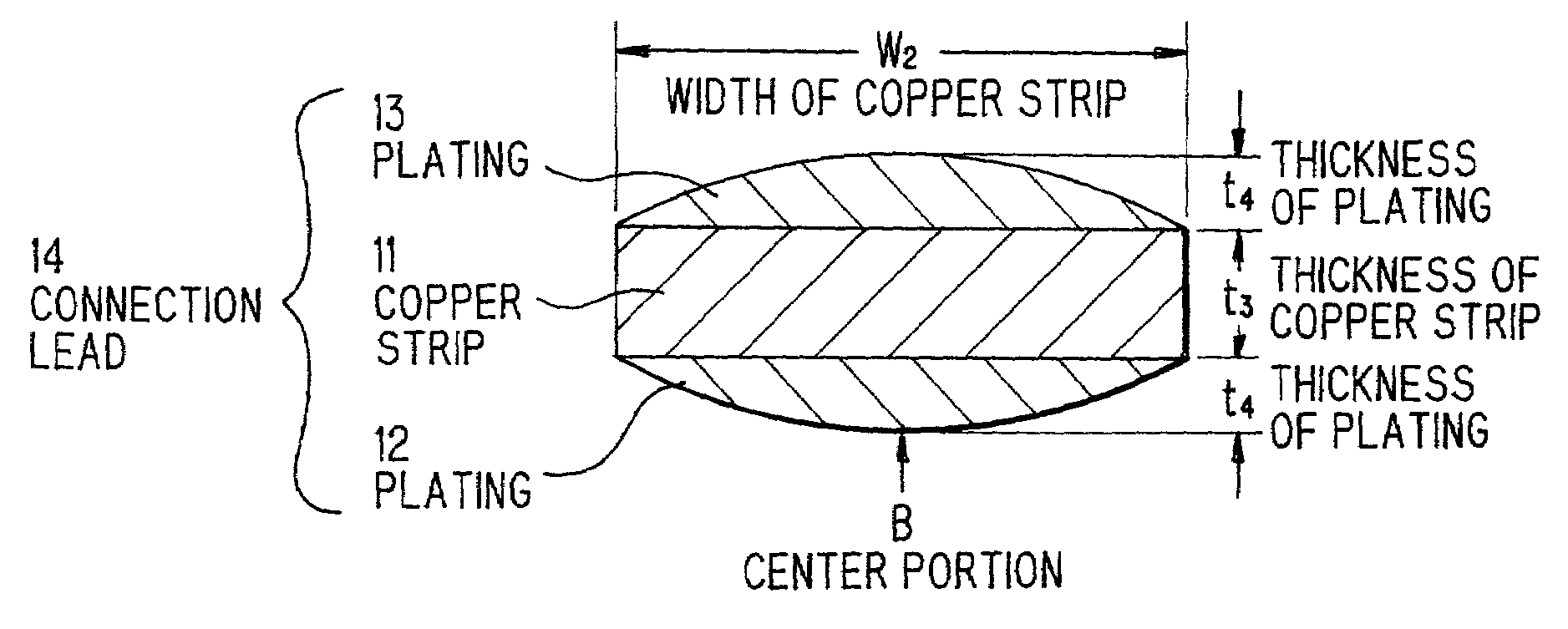
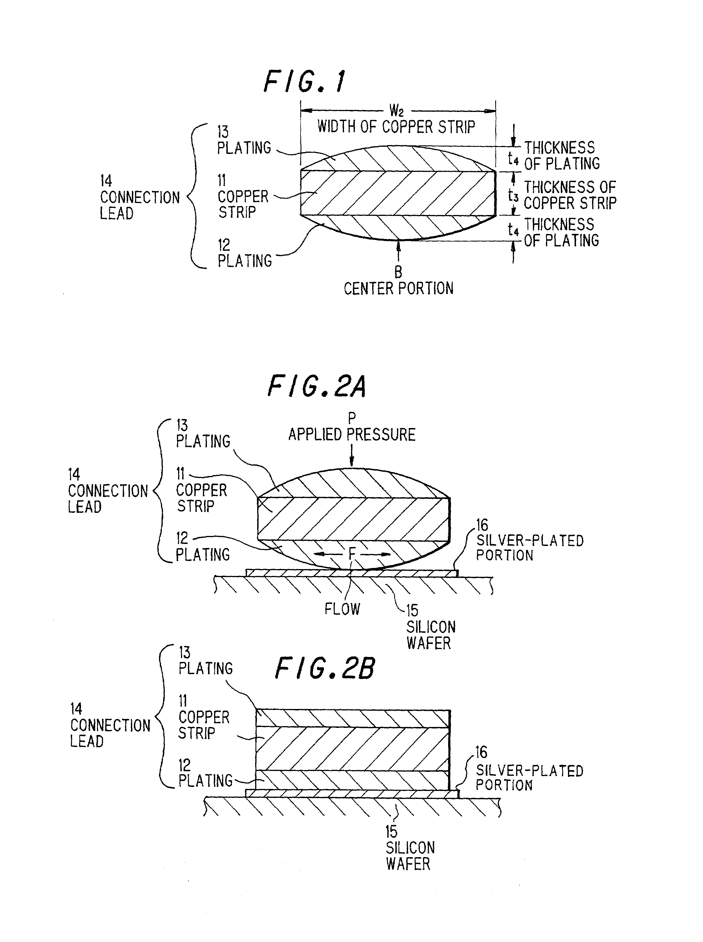
[0051]FIG. 1 shows a preferred embodiment of the connection lead according to the invention. In the drawing, numeral 14 designates a connection lead, numeral 11 a copper strip, and numerals 12 and 13 platings, formed of the lead-free solder according to the invention, provided respectively on both sides of the copper strip 11. In this case, each of the platings is in an arc sectional form such that the apex is located at the center portion B in the widthwise direction of the copper strip 11.

[0052]FIG. 2 is a diagram showing a construction wherein the connection lead 14 shown in FIG. 1 has been applied to a lead connection structure in a solar battery of the same type as shown in FIG. 6. As is demonstrated in the experimental results below, the lead-free solder, according to the invention, constituting the plating 12 is less likely to form an oxide layer and can be connected, ...


PUM

PropertyMeasurementUnit
Percent by massaaaaaaaaaa

Abstract

In a lead-free solder comprising an alloy composition composed mainly of tin, the alloy composition further contains 0.002 to 0.015% by mass of phosphorus. This lead-free solder can be used as a plating in a connection lead comprising: a copper strip or other strip conductor; and the plating provided on at least one side of the strip constructor, the plating having a shape such that the plating in the widthwise direction of the strip conductor has a bulge as viewed in section with the apex being located at a proper position in the widthwise direction of the strip conductor. By virtue of this constitution, the lead-free solder on its surface is less likely to be oxidized, and the connection lead has excellent bond strength owing to the property of the lead-free solder and, in addition, has the function of breaking the formed oxide layer and the function of removing included gas bubbles and can eliminate the need to form the plating in very large thickness. Further, the lead-free solder can be used as a connection element in an electrical component that is less likely to cause oxidation of the connection element on its surface and, thus, can have a strong connection structure by the connection element.

Description

FIELD OF THE INVENTION[0001]The invention relates to a lead-free solder, and a connection lead and an electrical component using said lead-free solder, and more particularly to a lead-free solder having a highly oxidation-resistant surface, a connection lead, which has excellent bond strength owing to the property of the lead-free solder and, in addition, has the function of breaking the formed oxide layer and the function of removing included gas bubbles and can eliminate the need to form a plating in very large thickness, and an electrical component which, by virtue of the application of the lead-free solder, is less likely to cause oxidation of the connection element on its surface and, thus, can realize a strong connection structure by the connection element.BACKGROUND OF THE INVENTION[0002]A semiconductor chip comprising a silicon crystal grown on a substrate has been utilized as a solar battery. The construction of this solar battery is generally such that a connection lead is...

Claims


Application Information

Patent Timeline
IPC IPC(8): H05K1/16C22C13/00B23K35/26C25D7/00H01B5/02H01L23/49H05K3/34
CPCB23K35/262H01L31/0504H01L31/0508H01L31/0512H05K3/3426H05K3/3463Y02E10/50
Inventor AOYAMA, SEIGIICHIKAWA, TAKAAKIKURODA, HIROMITSUNEMOTO, TAKASHIOHTAKE, ATSUSHIHIRUTA, HIROYOSHI
Owner HITACHI CABLE
Why Eureka
Try Eureka