Manure separator

a manure separator and separator technology, applied in the field of manure disposal for farms, can solve the problems of unneeded weight of manure, unnecessarily compacting soil, and compacting manure, and achieve the effect of efficient breakage of manure entering, convenient hauling of products, and reducing the number of problems

Inactive Publication Date: 2006-11-02
SHEAHAN DONALD T
View PDF22 Cites 13 Cited by
  • Summary
  • Abstract
  • Description
  • Claims
  • Application Information

AI Technical Summary

Benefits of technology

[0005] The present invention minimizes these problems. Water and air are used together to remove the sand from manure. A first separator or container having means for agitating the water and air will efficiently break up manure entering into the device. The device allows sand to drop to the bottom of the container quickly, which allows the manure solids to float to the surface of the container and to be removed. A second separator containing a spinning device or container will then use centrifugal force to separate the water and the manure solids removed from the first separator. The separation of the water from the separated manure provides for a more useable manure and, also, an easier to haul product. Furthermore, this is beneficial in not only reducing the weight of the manure, but, also, in removing more bacteria and similar unwanted organisms from the manure than in previous separator designs.

Problems solved by technology

While the sand provides comfort for the cows, it is a problem within manure pits and, also, a problem when hauling away the manure.
The sand in the manure adds unneeded weight to the manure, directly and indirectly with extra water being retained in the mix, which unnecessarily compacts soil when the manure is used as a fertilizer.
However, the manure solids and water still are combined, which results in the same problems of compacted manure.
The compacted manure results in a lower yield in the crops to which the manure is applied.
Furthermore, the weight of the water in the manure makes the manure more difficult to haul and transport.
Storage of the wet manure is also a problem, as the water in the manure leads to an increase in the amount of bacteria and decreases the usefulness of the manure.

Method used


Image

  • Manure separator
  • Manure separator
  • Manure separator

Examples


Embodiment Construction

[0015] Although the disclosure hereof is detailed and exact to enable those skilled in the art to practice the invention, the physical embodiments herein disclosed merely exemplify the invention which may be embodied in other specific structures. While the preferred embodiment has been described, the details may be changed without departing from the invention, which is defined by the claims.

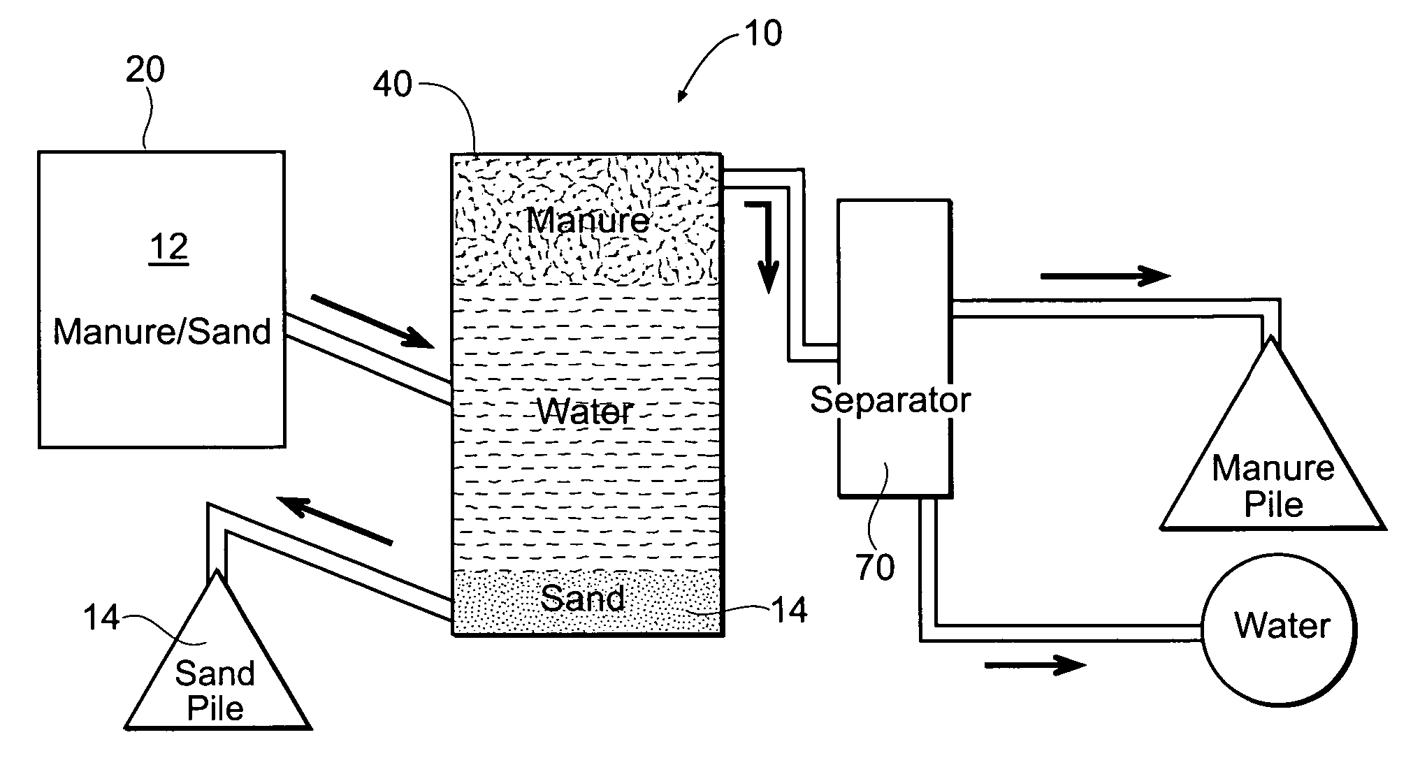
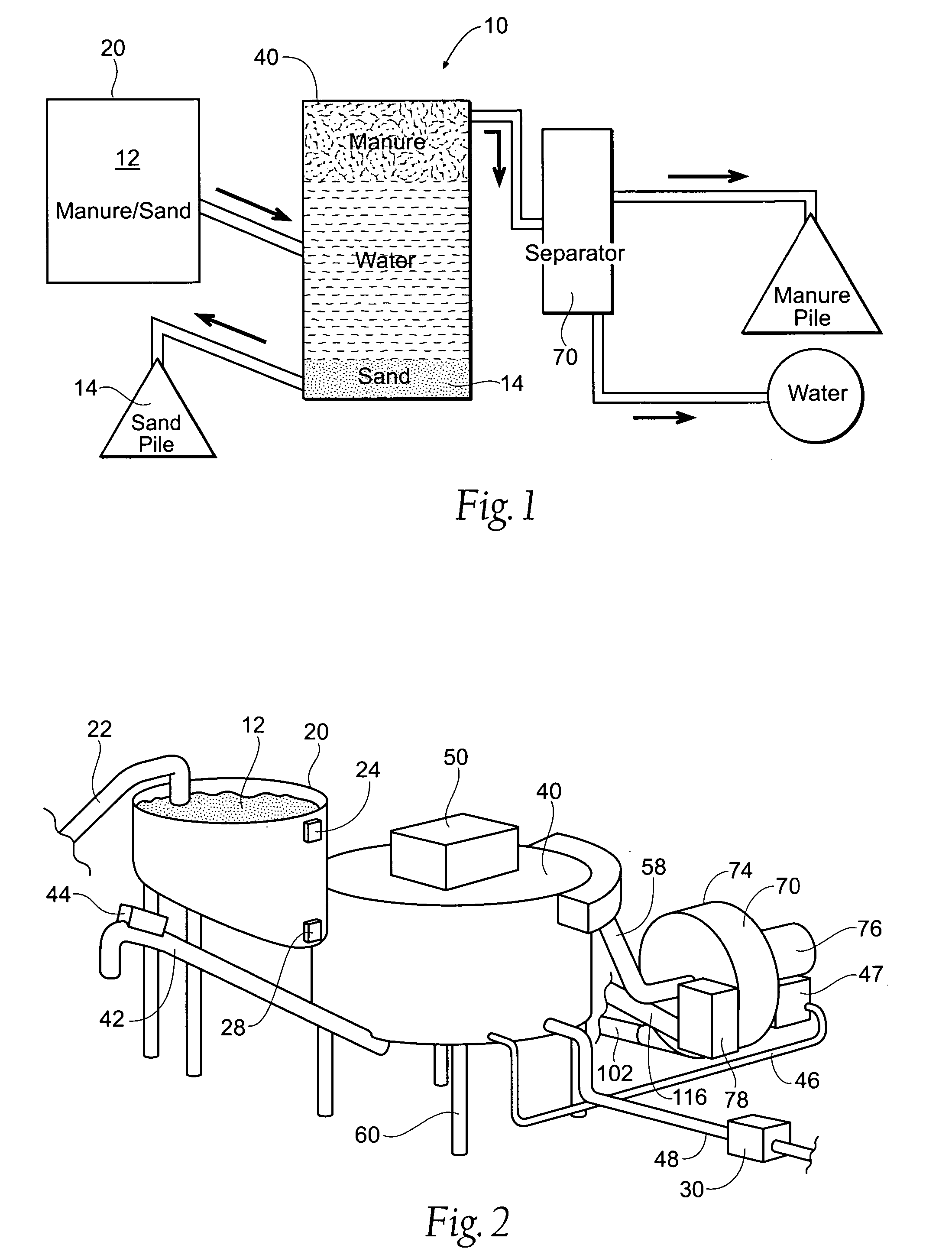
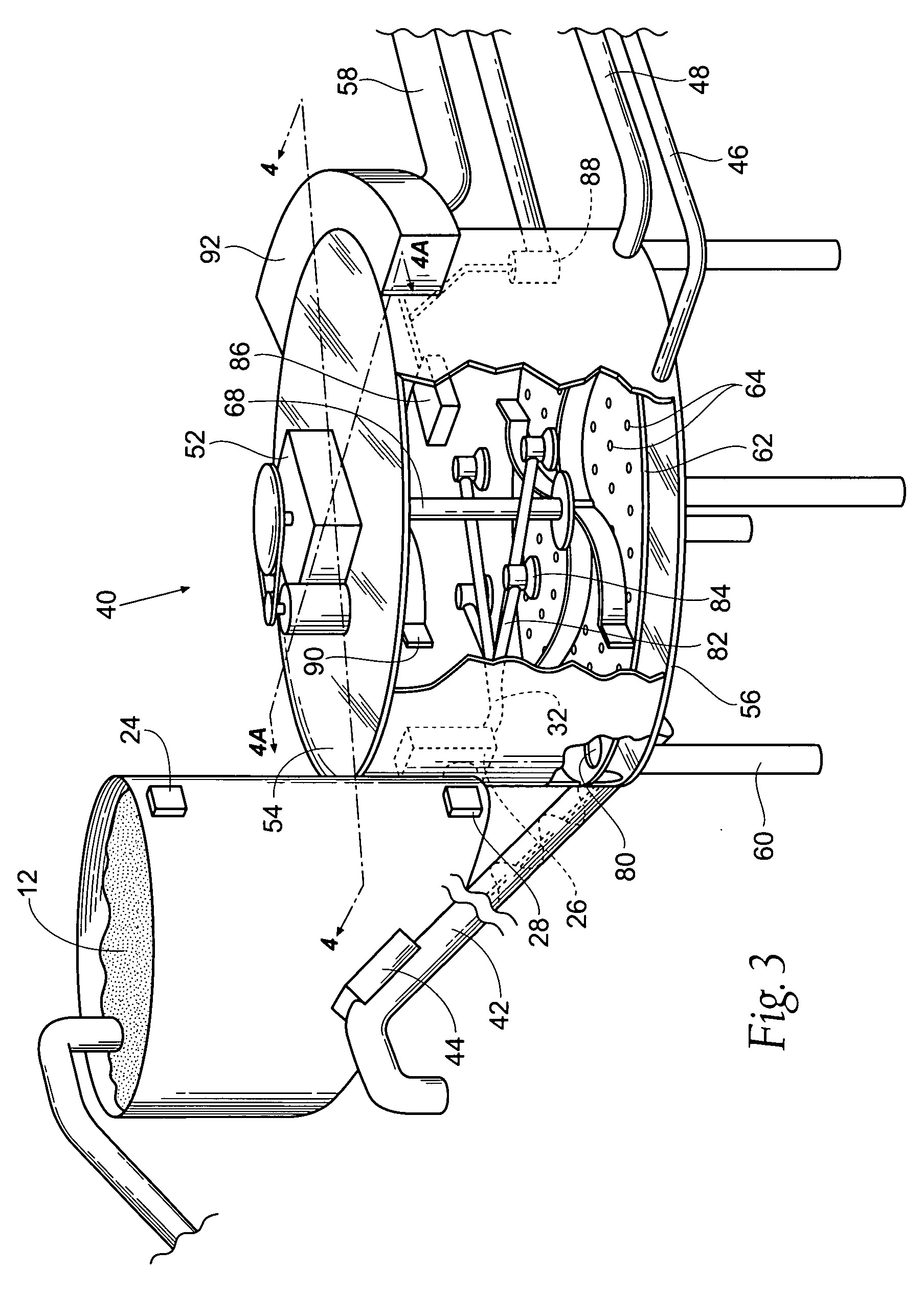
[0016]FIG. 1 shows a diagrammatic representation of a manure separating system 10 according to the present invention. The system 10 comprises a holding tank 20 for storing manure 12, a separator 40 for removing sand 14 and solids from the manure 12, and a second separator 70 for removing excess water from the manure 12. The system 10 allows for sand 14 to be recycled and used again as bedding for livestock and, also, the system 10 allows for the manure 12 to be used as an efficient future fertilizer. Because the system 10 provides for drier resultant manure than previous methods and apparatuses,...


PUM

PropertyMeasurementUnit
centrifugal forceaaaaaaaaaa
weightaaaaaaaaaa
structuresaaaaaaaaaa

Abstract

An apparatus and system for separating manure and sand in animal bedding is disclosed. The system separates the manure and sand by using a separator filled with water that agitates the sand / manure mixture with air and water. The manure removed from the separator is further processed to remove excess water from the manure. A spinning or centrifugal device is used to remove excess water from the manure.

Description

BACKGROUND OF THE INVENTION [0001] The following invention is related to manure disposal for farms, and specifically to machines that separate manure / sand mixtures for hauling and storage purposes. More specifically, the present invention relates to separators for separating or removing sand and water from manure. [0002] Many dairy farmers use sand as bedding for stalls within a barn. While the sand provides comfort for the cows, it is a problem within manure pits and, also, a problem when hauling away the manure. The sand in the manure adds unneeded weight to the manure, directly and indirectly with extra water being retained in the mix, which unnecessarily compacts soil when the manure is used as a fertilizer. Also, the manure / sand mix is more of a pollutant to the environment than manure itself. [0003] Machines have been designed to separate sand from the manure solids. An example of such a device can be found in Wedel, U.S. Pat. No. 5,950,839. The device uses water and air in co...

Claims


Application Information

Patent Timeline
Patent Type & Authority Applications(United States)
IPC IPC(8): C02F11/12B01D21/00B01D36/04
CPCA01C3/026B03D1/028B01D21/0024B01D21/02B01D21/2416B01D21/2433B01D21/2461B03D1/22B04B3/00B04B11/02C05F3/00A01K1/0114B01D2221/06B01D21/262B03D1/247B03D1/1468B03D1/1462B01D21/26C05F3/06Y02P20/145B01D21/34B03B5/623Y02A40/20Y02A40/28
Inventor SHEAHAN, DONALD T.
Owner SHEAHAN DONALD T
Why Eureka
Try Eureka