Vehicle frame structure

a frame structure and vehicle technology, applied in the direction of vehicle components, bumpers, superstructure sub-units, etc., can solve the problems of not being able to easily bend and bend efficiently, the breaking position of the side frame will not be stable, and the side structure will not be able to easily break and deform toward the inner side of the vehicle, so as to achieve efficient break and deformation

Active Publication Date: 2017-10-17
TOYOTA JIDOSHA KK
View PDF10 Cites 1 Cited by
  • Summary
  • Abstract
  • Description
  • Claims
  • Application Information

AI Technical Summary

Benefits of technology

[0010]In the above aspect, a width in a vehicle up and down direction of the first protruding structure may become wider farther away from the second protruding structure, in the vehicle front-rear direction.
[0026]On the other hand, when a collision load when a high speed collision occurs is input to the bumper reinforcement, the side structure is able to efficiently break and deform toward the inner side of the vehicle in the vehicle width direction at the connecting positions of the end portion of the first protruding structure that is on the opposite side from the crush box.

Problems solved by technology

However, with the related art, the edge line of the protruding portion formed on the outer side of the side frame terminates on a middle of the side frame in a height direction of the outer side surface of the side frame, so the breaking position of the side frame will not be stable when a collision occurs.
On the flip side, the side frame will probably not easily bend efficiently at the initial (first stage) breaking position by only providing the protruding portion on the side frame side.
Therefore, if the end portion of the first protruding structure that is on the opposite side from the crush box is set in the position where the engine mount attaching structure is arranged, the side structure will not easily break and deform toward the inner side of the vehicle in the vehicle width direction when a collision occurs.
As a result, loss would occur in the transmission of a collision load.

Method used


Image

  • Vehicle frame structure
  • Vehicle frame structure
  • Vehicle frame structure

Examples


Embodiment Construction

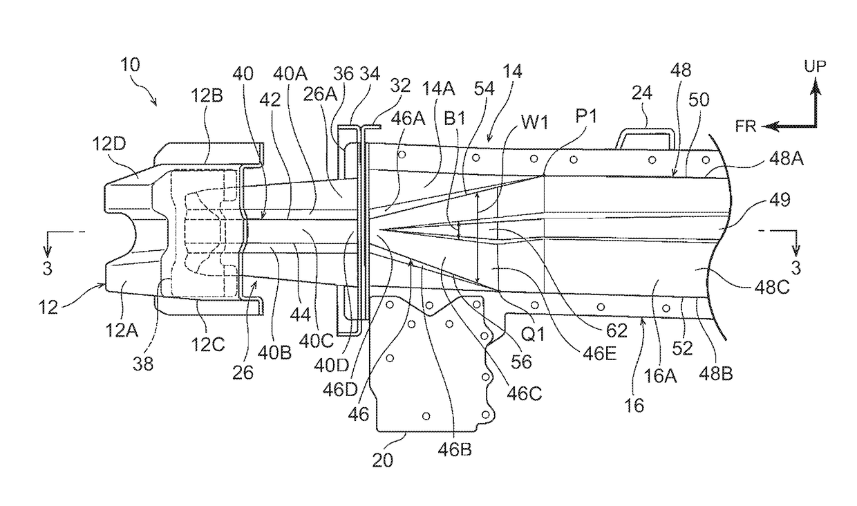
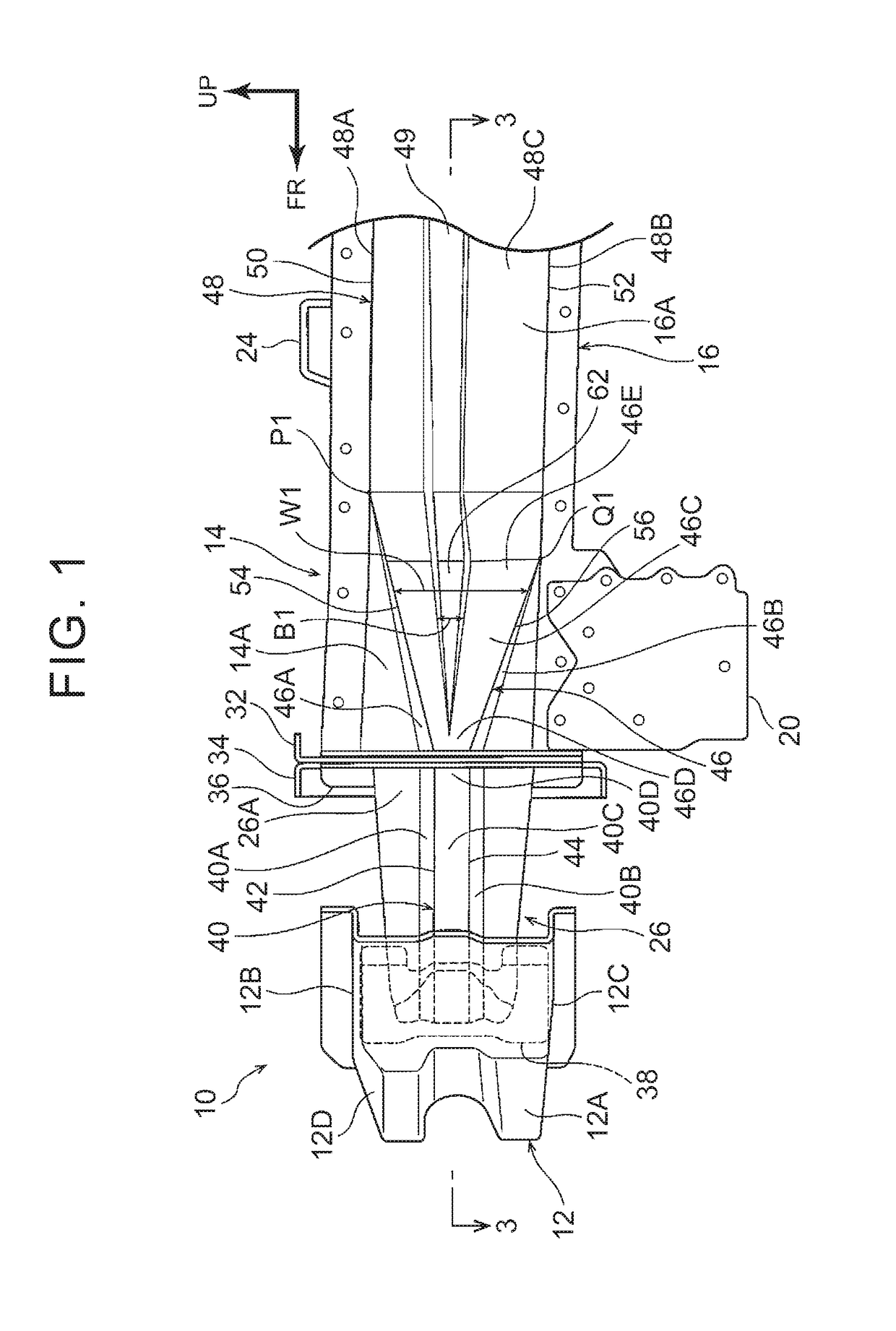
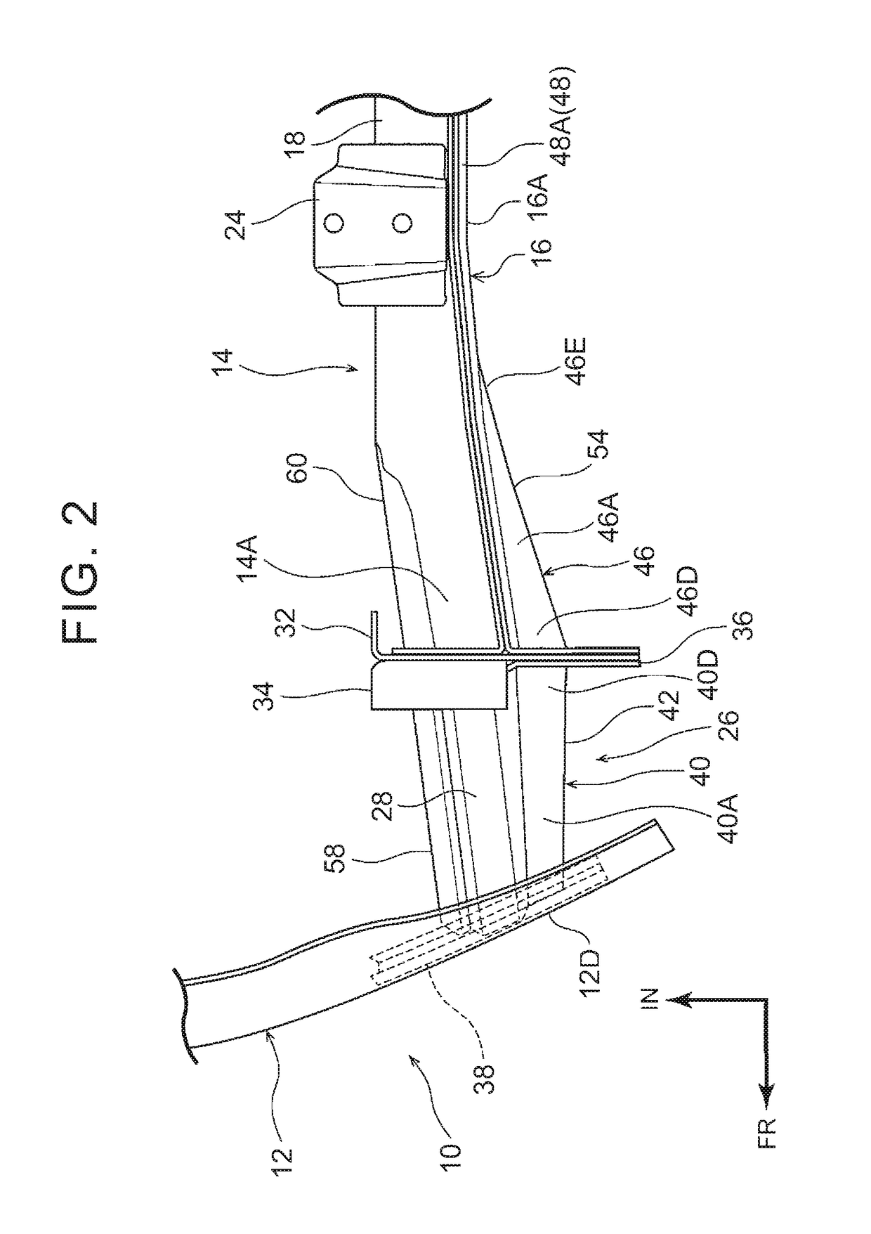
[0036]Hereinafter, a vehicle frame structure according to a first example embodiment of the disclosure will be described with reference to FIGS. 1 to 4. In the drawings, the arrow FR indicates a vehicle front side, and the arrow RR indicates a vehicle rear side. Also, the arrow UP indicates a vehicle upper side, and the arrow IN indicates the inside in a vehicle width direction. Also, although FIGS. 1 to 4 show a left front portion of a vehicle, the vehicle frame structure of the disclosure is a bilaterally symmetrical structure.

[0037]As shown in FIGS. 1 to 4, a front bumper reinforcement 12 that extends in the vehicle width direction is arranged on a front end portion of a vehicle body front portion 10 in a vehicle front-rear direction. This front bumper reinforcement 12 is an open cross-sectional structure. More specifically, the front bumper reinforcement 12 is formed in a general hat shape that is open on the vehicle rear side, and includes a front wall portion 12A that extends ...


PUM


Abstract

A vehicle frame structure includes a bumper reinforcement, a side structure that includes a first side wall on an outer side of the side structure in a vehicle width direction and a first protruding structure, and a crush box that is arranged between the bumper reinforcement and the side structure and includes a second side wall on an outer side of the crush box in the vehicle width direction, the second side wall having a second protruding structure. An edge line of the first protruding structure and an edge line of the second protruding structure are provided to be continuous in a vehicle front-rear direction, and a width in a vehicle up and down direction of the first protruding structure becomes wider farther away from the second protruding structure, in the vehicle front-rear direction.

Description

CROSS-REFERENCE TO RELATED APPLICATIONS[0001]This application is based upon and claims the benefit of priority from Japanese Patent Application No, 2015-164084, filed on Aug. 21, 2015, the entire contents of which are incorporated herein by reference in entirety.BACKGROUND OF THE DISCLOSURE[0002]1. Field of the Disclosure[0003]This application relates to a vehicle frame structure.[0004]2. Description of Related Art[0005]Japanese Patent Application Publication No. 2013-014289 (JP 2013-014289 A) described below describes technology relating to a front vehicle body structure of a vehicle. In brief, with this related art, a protruding portion that protrudes toward an outside of the vehicle in a vehicle width direction is formed on both an outer side surface of a crush box and an outer side surface of a side frame. This protruding portion has a U-shaped sectional shape that is open on an inner side in a vehicle width direction. An edge line of the protruding portion on the crush box side...

Claims


Application Information

Patent Timeline
Patent Type & Authority Patents(United States)
IPC IPC(8): B60R19/34B62D21/15B60R19/42B62D25/08
CPCB60R19/34B60R19/42B62D21/152B62D25/082
Inventor TAGUCHI, KOSUKESUGANO, CHITOSHI
Owner TOYOTA JIDOSHA KK
Why Eureka
Try Eureka