Water Purifying Apparatus

a technology of water purification apparatus and water droplets, which is applied in the direction of chemistry apparatus and processes, separation processes, evaporation, etc., can solve the problems of 1.1 billion people in the world's population facing a situation where they cannot use water in sufficient quantities, and achieve the effect of facilitating deformation of raw water, improving collection efficiency, and efficiently breaking or splitting raw water into droplets

Inactive Publication Date: 2012-07-12
CIP SOFTWARE
View PDF13 Cites 6 Cited by
  • Summary
  • Abstract
  • Description
  • Claims
  • Application Information

AI Technical Summary

Benefits of technology

[0030]In the water purifying apparatus according to the first aspect of the present invention, the blade has irregularities, so that it becomes possible to facilitate deforming raw water and efficiently break or split the raw water into droplets to improve efficiency for collecting purified water from raw water.
[0031]The blade may be disposed obliquely with respect to its rotational axis. In this case, when raw water hits against the blade, it pushed the blade in a rotation direction of the blade to accelerate the rotation of the blade, so that it becomes possible to facilitate splitting (breaking) the raw water into droplets and creating the carrier airflow.
[0032]The blade may be formed by cutting a disk-shaped member in a radial direction thereof to prepare a sector-shaped piece, and twisting the sector-shaped piece. In this case, the blade can be fabricated in a simple process.
[0033]The water purifying apparatus may comprise a circulator attached to the rotary shaft of the splitter device. In this case, the circulator can be provided in a space-saving manner.
[0034]The condenser may include the first condenser and the second conde

Problems solved by technology

Currently, 1.1 billion people in the world's population f

Method used


Image

  • Water Purifying Apparatus
  • Water Purifying Apparatus
  • Water Purifying Apparatus

Examples


first embodiment

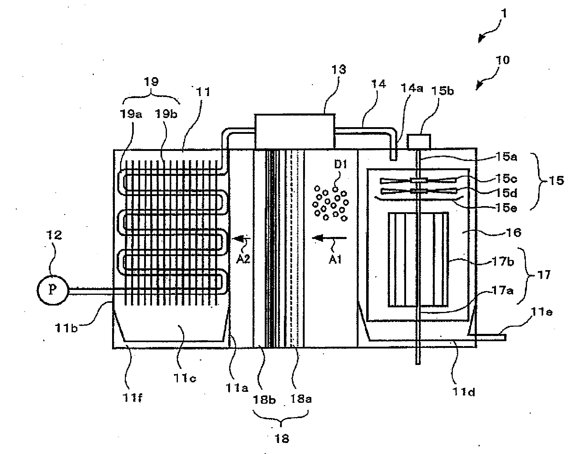
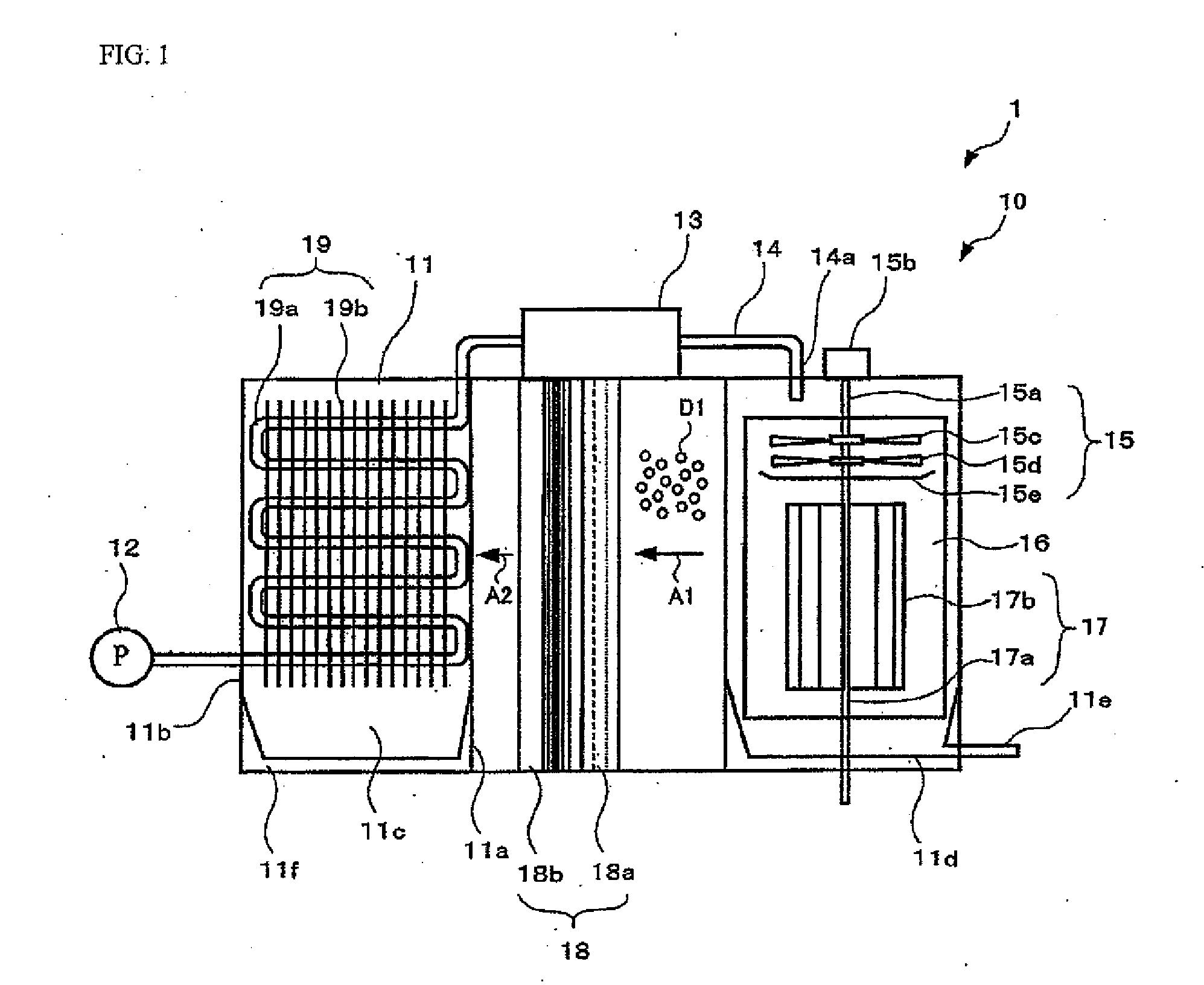
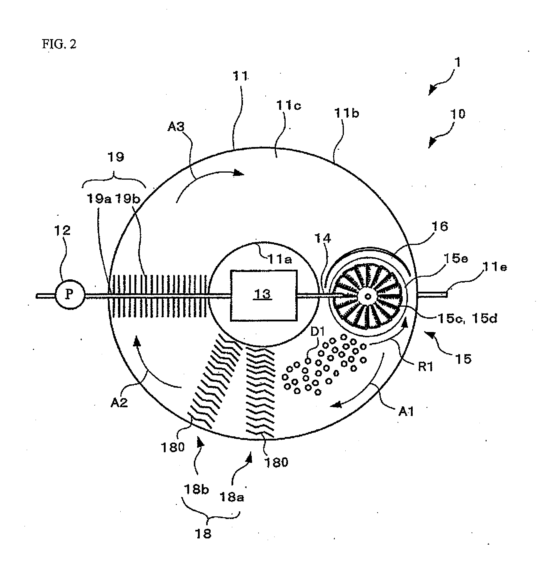
[0056]As illustrated in FIGS. 1 and 2, a water purifying apparatus 1 has an evaporation-condensation system 10. This system 10 comprises an annular-shaped casing 11 adapted to permit circulation of airflow therethrough, a pump 12 disposed outside the casing 11, and a heater 13 disposed on a top of the casing 11. The water purifying apparatus 1 comprises a splitter device 15 disposed within the casing 11 and below the heater 13, and a guide 16 disposed behind the splitter device 15, and a circulator 17 disposed in coaxial relation with the splitter device 15 and having a fan, such as a sirocco fan. The water purifying apparatus 1 further comprises a demister group 18 comprising demisters 18a and 18b, and a condenser 19 disposed downstream of the demister group 18.

[0057]The casing 11 comprises an inner cylinder 11a, an outer cylinder 11b disposed outside the inner cylinder 11a, and an annular space 11c defined between the inner cylinder 11a and the outer cylinder 11b. This space 11e i...

second embodiment

[0092]As illustrated in FIG. 8, a water purifying apparatus 1A according to a second embodiment of the present invention has a modified demister 18C. The demister 18C comprises a demister plate group 18c. The demister plate group 18c consists of a plurality of demister plates 180C arranged in mutually spaced-apart relation, i.e., at interval of a predetermined distance, to defined a flow passage therebetween. As illustrated in FIG. 9, each of the demister plates 180C is composed of one sheet 181 curved along a plurality of lines 181a, 181b, 181c, 181d. Each of the demister plates 180C is formed in a wave shape which has a plurality of valley portions 181a, 181c, 181d, and a plurality of crest portions 181b, 181d each located between adjacent ones of the valley portions 181a, 181c, 181d. Adjacent ones of the demister plates 180C define an S-shaped meandering flow passage.

[0093]In the second embodiment, a carrier airflow A1 with water vapor and droplets flows between adjacent ones 180...

fourth embodiment

[0105]As illustrated in FIG. 13, a water purifying apparatus 1C according to a fourth embodiment of the present invention has a two-tiered structure of lower and upper evaporation-condensation systems 10A, 10B. Each of the lower and upper systems 10A, 10B comprises a casing (11A, 11B), a splitter device (15A, 15B), a circulator (17A, 17B), a demister (18A, 18B) and a condenser (19A, 19B), each which is identical to a corresponding one of the components in the first embodiment.

[0106]The lower and upper casings 11A, 11B have a commutation pipe 21 communicating therebetween. The communication pipe 21 is adapted to introduce raw water from an upper liquid receiver 11d of the upper casing 11B to the lower casing 11A. The lower and upper casings 11A, 11B further have an outlet pipe 23 connected to respective outlet pipes 11g, 11g of upper and lower liquid receivers 11f, 11f of the upper and lower casings 11A, 11B.

[0107]The lower splitter device 15A and the upper splitter device 15B have a...


PUM

PropertyMeasurementUnit
Temperatureaaaaaaaaaa
Massaaaaaaaaaa
Massaaaaaaaaaa

Abstract

Provided is a water purifying apparatus capable of efficiently producing purified water from raw water. The water purifying apparatus comprises: a casing (11) having a circulation path; a splitter device (15) disposed within the casing (11) and adapted to split raw water into droplets and create a carrier airflow (A1) capable of circulating along the circulation path and carrying water vapor evaporated from the droplets (D1); and a condenser (19) disposed within the casing (11) at a position downstream of the splitter device (15) in a direction of the carrier airflow and adapted to condense the water vapor to create purified water. The splitter device (15) comprises a rotary shaft (15a) extending in an up-down direction of the casing (11), and a blade (152A to 152Q) radially attached to the rotary shaft (15a) and having irregularities (152p, 152q, 152r, 152s, 152t).

Description

TECHNICAL FIELD[0001]The present invention relates to a water purifying apparatus for obtaining purified water from raw water.BACKGROUND ART[0002]Currently, 1.1 billion people in the world's population face a situation where they cannot sufficiently use water. It is predicted that, in 2025, 3 billion people will suffer from water shortage. In view of this issue, various apparatuses for obtaining freshwater from seawater are being studied. Particularly, in recent years, a reverse osmosis membrane apparatus designed to subject seawater to filtering to create freshwater, and an evaporation apparatus designed to distill seawater to create freshwater, have been put to practical use.[0003]For example, a multi-stage evaporation apparatus has a plurality of depressurization chambers. Each of the chambers is depressurized to lower an evaporation temperature to induce evaporation of seawater. Condensation heat of water vapor evaporated in a high-temperature one of the chambers is heat-exchang...

Claims


Application Information

Patent Timeline
IPC IPC(8): B01D3/08
CPCB01D1/16C02F1/14C02F1/12B01D5/006Y02W10/37B01D3/343B01D1/0094B01D1/305C02F1/04C02F2103/08
Inventor YABE, TAKASHI
Owner CIP SOFTWARE
Why Eureka
Try Eureka