
Iron clud head

a technology of iron club head and clud head, which is applied in the field of iron club head, can solve the problems of ineffective expansion of the elastic deformation area of the striking plate b>2/b>, adverse affect the coefficient of restitution of the body, etc., and achieve the effect of improving the overall elastic deformation capacity of the iron club head

Inactive Publication Date: 2005-11-17
FUSHENG IND CO LTD
View PDF10 Cites 39 Cited by
  • Summary
  • Abstract
  • Description
  • Claims
  • Application Information

AI Technical Summary

Benefits of technology

[0007] An object of the present invention is to provide an iron club head including a body and a striking plate having a thickness greater than that of the body to improve the overall elastic deforming capacity of the iron club head. SUMMARY OF THE INVENTION
[0009] When the iron club head hits a golf ball, a momentum of striking generated as a result of hitting the golf ball causes elastic deformation of the striking plate and the thin wall to increase an overall deformation of the iron club head.

Problems solved by technology

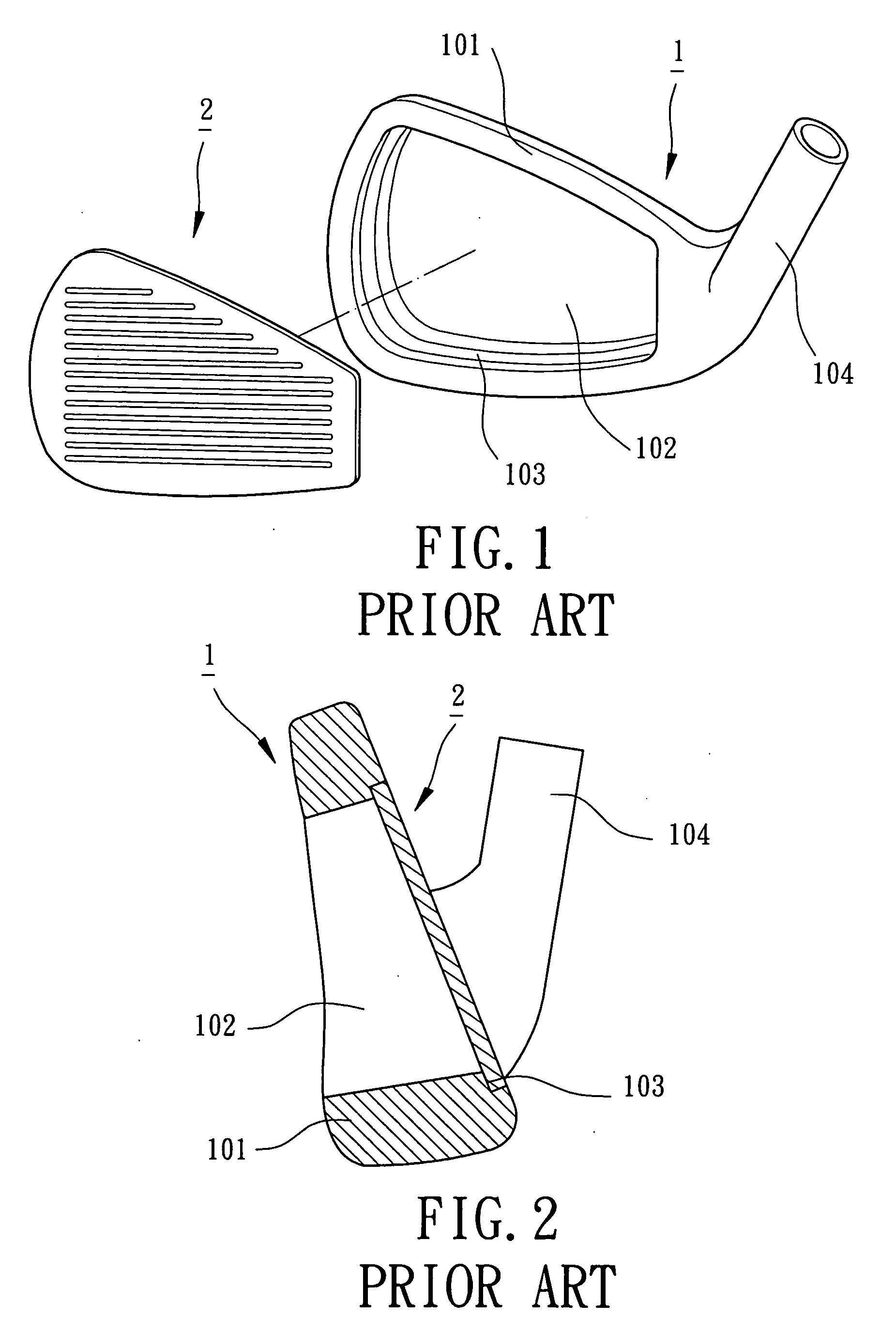
The coefficient of restitution of the body 1 is thus adversely affected.
Thus, the elastic deforming area of the striking plate 2 cannot be effectively expanded.

Method used


Image

  • Iron clud head
  • Iron clud head
  • Iron clud head

Examples


Embodiment Construction

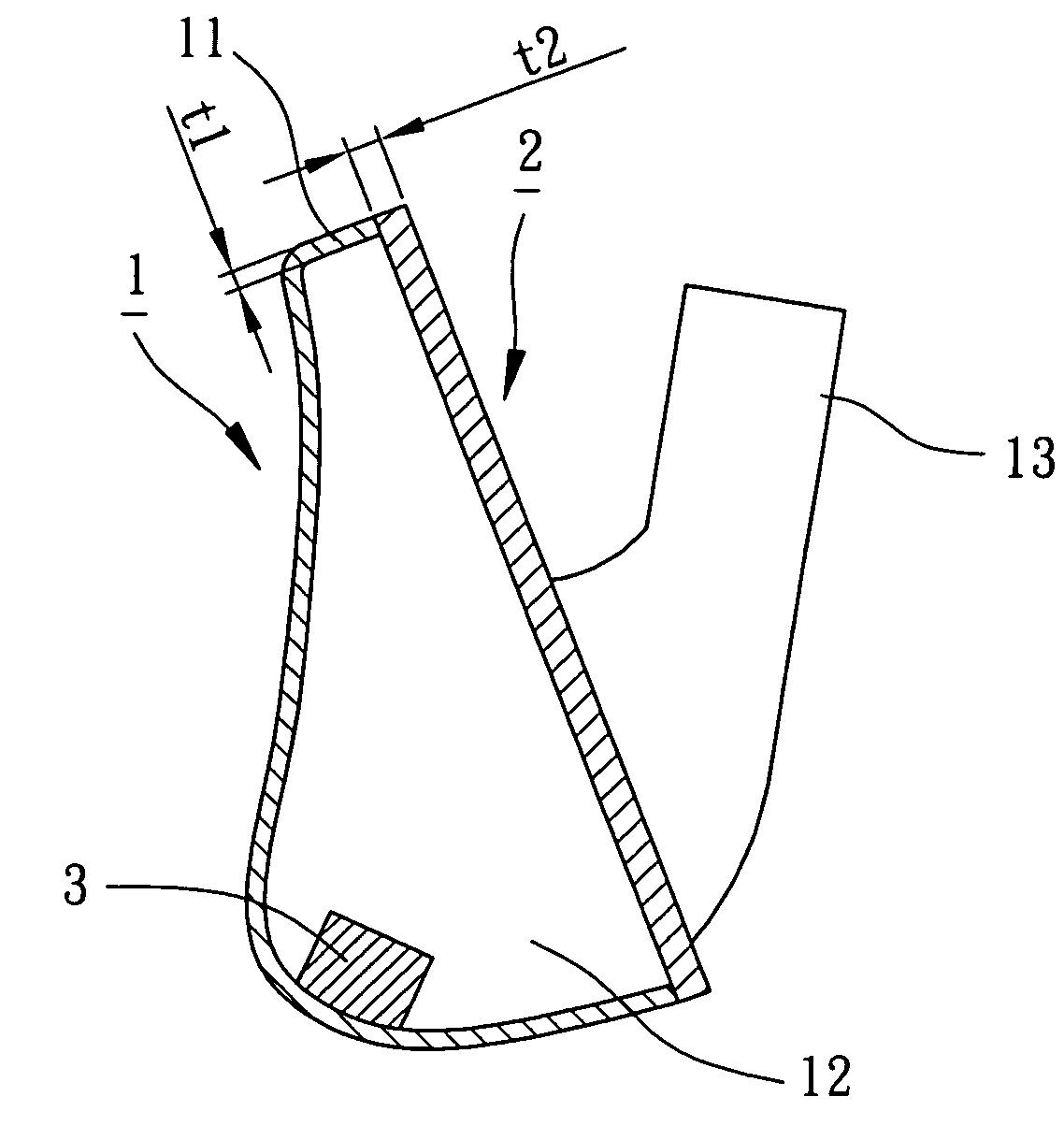
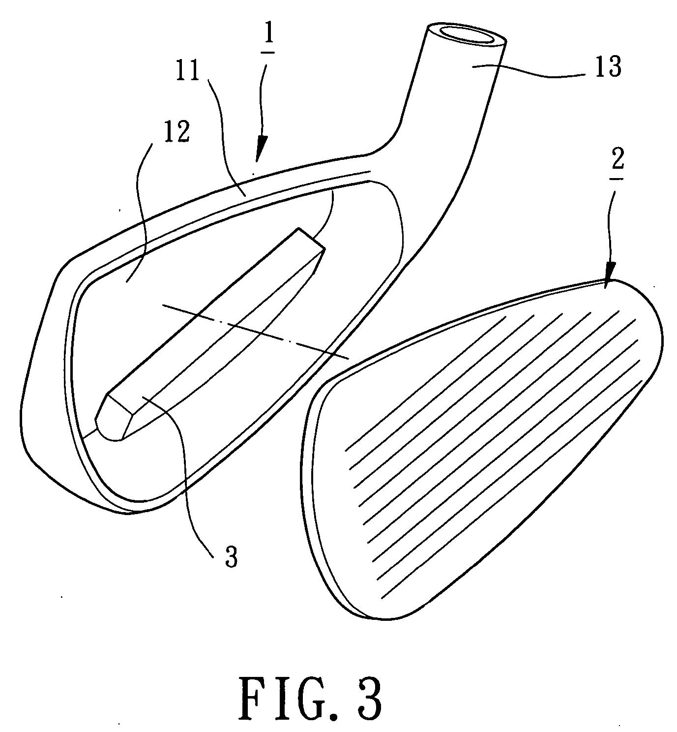
[0022] Referring to FIGS. 3 and 4, an iron club head in accordance with the present invention comprises a body 1, a striking plate 2, and a weight member 3. The body 1 includes an elastically deformable thin wall 11 and an opening 12 in a front side of the body 1. The thin wall 11 includes an open front side and a closed rear side and surrounds the opening 12 in the front side of the body 1. A hosel 13 extends from a side of the body 1 for engaging with a shaft (not shown). The thin wall 11 has a thickness t1 preferably between 0.5 mm and 2.0 mm, most preferably 0.7 mm and 1.5 mm. The thickness t1 of the thin wall 11 may be uniform throughout the thin wall 11 or varied within a range. The coefficient of restitution (COR) of the thin wall 11 can be increased by means of reducing the thickness t1 of the thin wall 11. Thus, adverse affection to the elastic deformation and momentum resulting from the damping effect of the material of the thin wall 1 is eliminated and / or obviated. In a c...


PUM


Abstract

An iron club head includes a striking plate for striking a golf ball and a body. The body includes an elastically deformable thin wall. An opening is defined in a front side of the body and surrounded by the thin wall. The striking plate is bonded in the opening. The thin wall has a thickness smaller than that of the striking plate. When the iron club head hits a golf ball, a momentum of striking generated as a result of hitting the golf ball causes elastic deformation of the striking plate and the thin wall to increase an overall deformation of the iron club head.

Description

BACKGROUND OF THE INVENTION [0001] 1. Field of the Invention [0002] The present invention relates to an iron club head. In particular, the present invention relates to an iron club head including a body and a striking plate having a thickness greater than that of the body to improve the overall elastic deforming capacity of the iron club head. [0003] 2. Description of Related Art [0004]FIGS. 1 and 2 of the drawings illustrate a typical iron club head comprising a body 1 and a striking plate 2. The body 1 includes an annular wall 101 delimiting an opening 102, with a hosel 104 extending from a side of the body 1 for engaging with a shaft (no shown). The striking plate 2 is supported by a stepped portion 103 of the opening 102. The body 1 and the striking plate 2 are generally engaged together to form an iron club head by means of welding, brazing, insertion, bonding, or screwing. When striking a golf ball with the iron club head, the striking plate 2 hits the golf ball and then defor...

Claims


Application Information

Patent Timeline
IPC IPC(8): A63B53/04A63B59/00
CPCA63B53/047A63B59/0092A63B2053/0433A63B2053/0491A63B2053/0416A63B60/02A63B60/54A63B53/0416A63B53/0433
Inventor HUANG, CHUNG-YUNG
Owner FUSHENG IND CO LTD
Learn More