

Distance sensor for vehicle with electrical connector
- Summary
- Abstract
- Description
- Claims
- Application Information
AI Technical Summary
Benefits of technology
Problems solved by technology
Method used
Image

Examples
Embodiment Construction
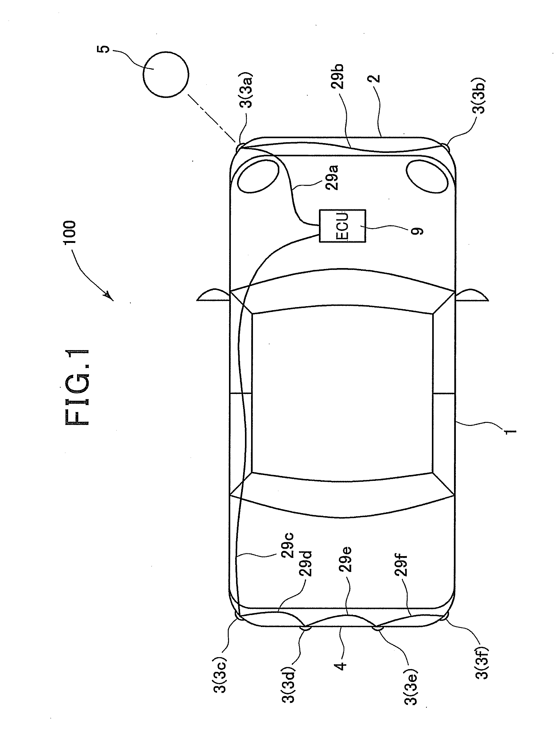
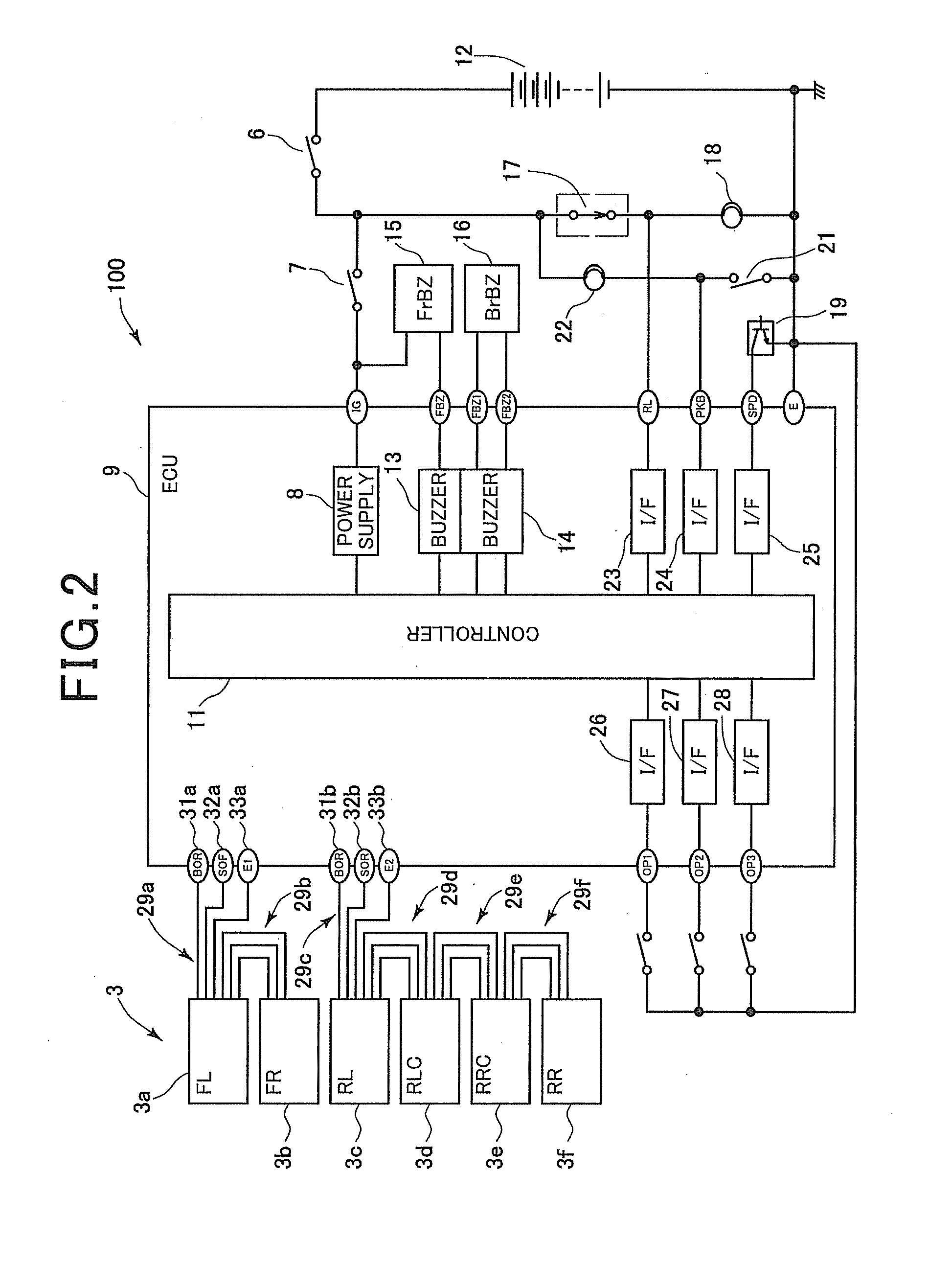
Referring to the drawings, wherein like reference numbers refer to like parts in several views, particularly to FIG. 1, there is shown an automotive obstacle detector 100 which is implemented by a clearance sonar system. The obstacle detector 100 are equipped with two front ultrasonic sensors 3a and 3b attached to left and right corners of a front bumper 2 of a motor vehicle 1 and three rear ultrasonic sensors 3c, 3d, 3e, and 3f attached to left and right corners and a middle portion of a rear bumper 4. These ultrasonic sensors will also be generally referred to by numeral 3 below. When a given condition is encountered, the ultrasonic sensor 3 is activated to transmit a radar wave in the form of an ultrasonic wave outward of the vehicle 1 and receive a return thereof (i.e., a radar echo) from an obstacle 5 to determine the distance between the vehicle 1 and the obstacle 5. When the distance to the obstacle 5 becomes smaller than a given value, the obstacle detector 100 alerts the dr...
PUM
 Abstract
Description
Claims
Application Information