Methods and systems for sizing an orthotic device

a technology for orthotics and foot, applied in the field of sizing an orthotic device for a foot, can solve the problems of not restoring the alignment of the foot structure (bones, joints, ligaments, etc.) to the physiologic natural condition, not optimizing the foot function, and other limitations of the related ar

Inactive Publication Date: 2017-01-12
LATTERMAN SUE ANN
View PDF12 Cites 5 Cited by
  • Summary
  • Abstract
  • Description
  • Claims
  • Application Information

AI Technical Summary

Benefits of technology

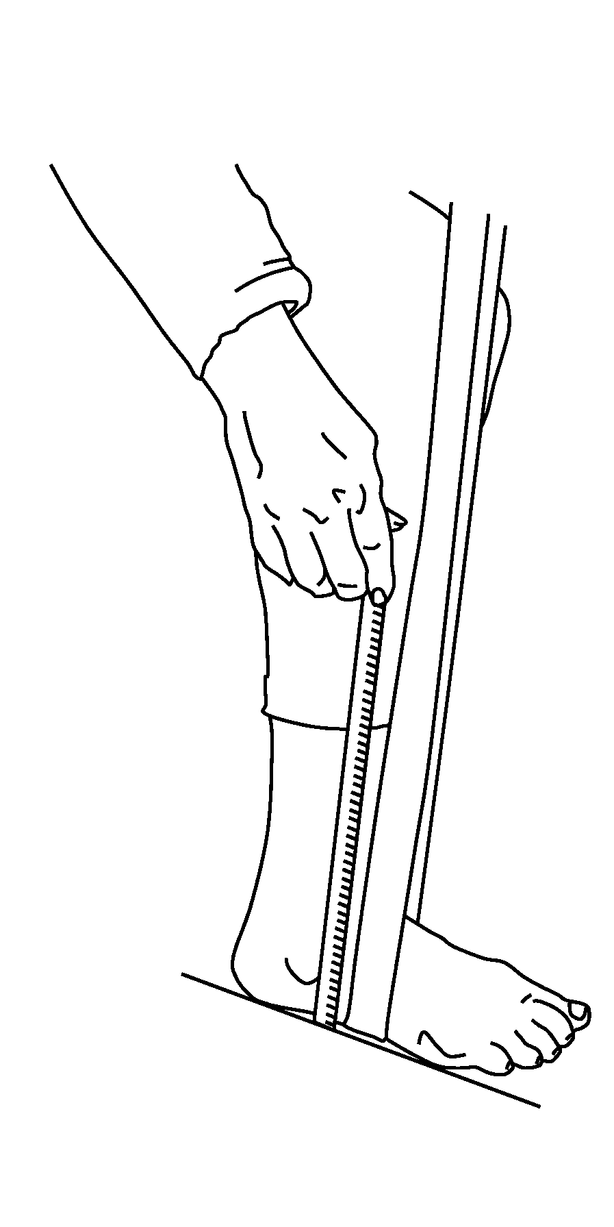
[0023]In some embodiments, height h is measured after manual or automated manipulation of the foot to adjust one or more bones in the midfoot to a restored state.
[0024]In another embodiment, recommending comprises recommending a size from a library of foot orthotics that comprises orthotics with a size that correlates to length l1. In another embodiment, recommending comprises recommending a size from a library of foot orthotics that comprises orthotics at one or more widths that accommodate measured width w. In still other embodiments, recommending a size comprises recommending a size that is based on length l1 and width w. In yet other embodiments, recommending a size comprises recommending a size that is based on length l1 or on height h. In another embodiment, recommending a size comprises recommending a size that is based on length l1 or on height h and additionally recommending a width of an orthotic based on width w.
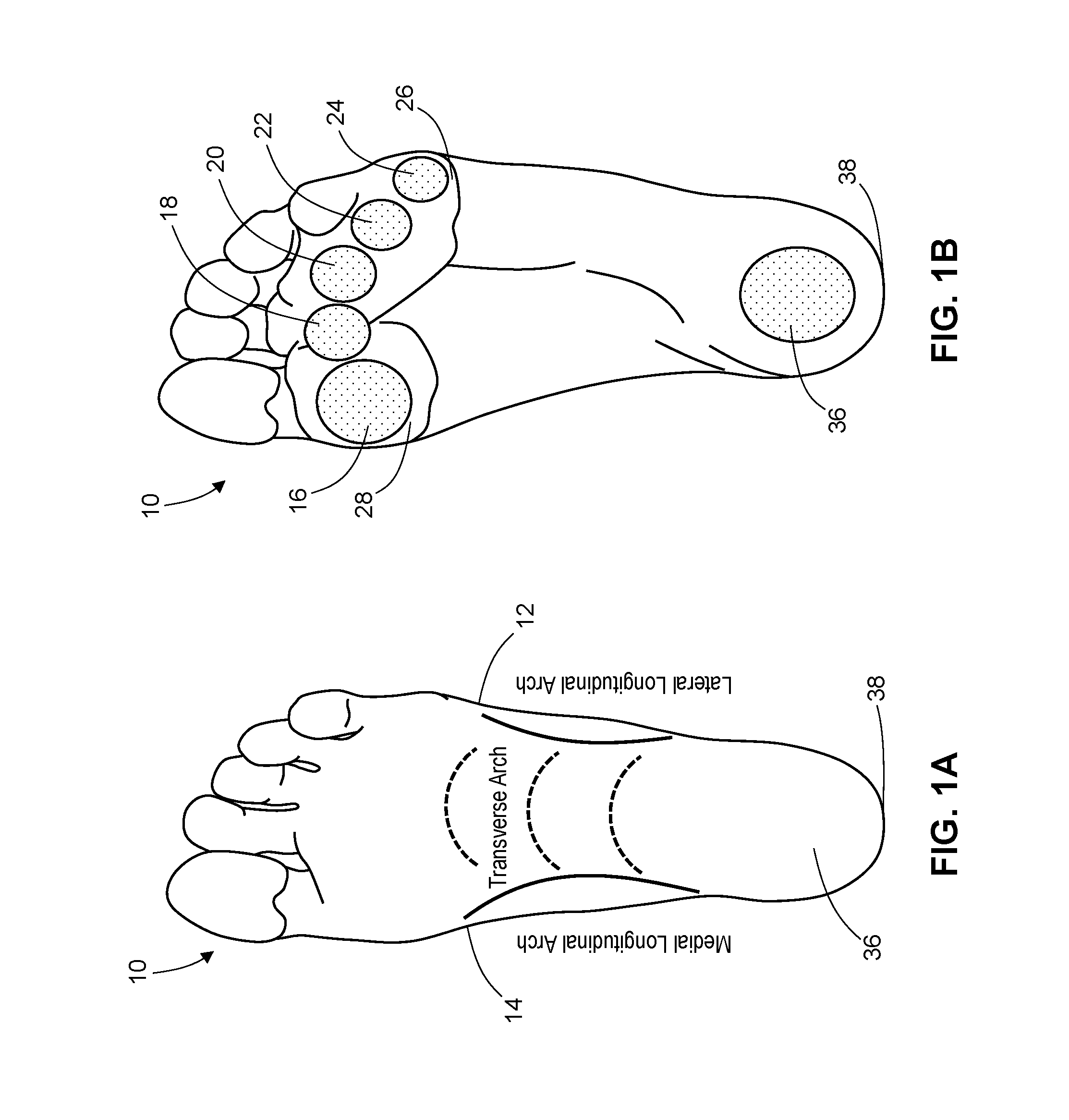
[0025]In some embodiments, recommending a size comprises recommending a size based on height h, where height h is correlated to a vacuity defined by medial, lateral and transverse foot arches relative to ground. In other embodiments, recommending a size comprises recommending a size based on height h, where height h is correlated to a volume v corresponding to a vacuity defined by the plantar topography of the foot and the ground while standing or while seated. In one embodiment, the vacuity has a volume v determined from a statistical average of measurements of the vacuity of feet in a population of feet after manipulation of each foot (manually or with an instrument) to position one or more bones in the midfoot to a restored state. The dimensions to determine volume of the vacuity are measured after manipulation of a foot, and the volume of vacuity is an average or median volume in a population of feet after manipulation of each foot. In one embodiment, the dimensions to ascertain volume of the vacuity are one or more of medial, lateral and transverse foot arches relative to a ground or plane.
[0026]In one embodiment, the volume v is selected from at least two volumes v1 and v2, which can be assigned an identifier, such as “low” or “medium”, where the at least two volumes v1 and v2 are determined from vacuity measurements of a population of feet manipulated into an adjusted or restored state. In one embodiment, the volume v is selected from 2, 3, 4 or 5 volumes assigned an identifier, such as v1, v2, v3, v4, and v5, or F, L, M, MH, H, where the at least two identified volumes were determined from vacuity measurements of a population of feet manipulated into an adjusted or restored state. The volume v can, in any of these embodiments, have a height dimension that is greater than the measured lateral arch height h by a numerical factor and / or that is less than a measured medial arch height relative to ground while sitting or standing or partially standing. In one embodiment, the measured medial arch height is reduced to an adjusted medial arch height such that the adjusted medial arch height is greater than the measured lateral arch height h by the numerical factor. The numerical factor can be a value between about 0.40-0.60 cm (0.16-0.24 inches), about 0.42-0.58 cm (about 0.16-0.23 inches), about 0.45 cm-0.64 cm (about 0.18-0.25 inches) or about 0.45-0.55 cm (about 0.18-0.22 inches), or about 0.47-0.52 cm (about 0.18-0.20) or about 0.38-0.76 cm (about 0.15-0.30 inches).

Problems solved by technology

These common approaches, however, do not restore alignment of the foot structures (bones, joints, ligaments, etc.) to the physiologic natural condition, and therefore do not optimize foot function.
Other limitations of the related art will become apparent to those of skill in the art upon a reading of the specification and a study of the drawings.

Method used


Image

  • Methods and systems for sizing an orthotic device
  • Methods and systems for sizing an orthotic device
  • Methods and systems for sizing an orthotic device

Examples


Embodiment Construction

I. Definitions

[0057]Various aspects now will be described more fully hereinafter. Such aspects may, however, be embodied in many different forms and should not be construed as limited to the embodiments set forth herein; rather, these embodiments are provided so that this disclosure will be thorough and complete, and will fully convey its scope to those skilled in the art.

[0058]Where a range of values is provided, it is intended that each intervening value between the upper and lower limit of that range and any other stated or intervening value in that stated range is encompassed within the disclosure. For example, if a range of 1 μm to 8 μm is stated, it is intended that 2 μm, 3 μm, 4 μm, 5 μm, 6 μm, and 7 μm are also explicitly disclosed, as well as the range of values greater than or equal to 1 μm and the range of values less than or equal to 8 μm.

[0059]The singular forms “a,”“an,” and “the” include plural referents unless the context clearly dictates otherwise. Thus, for example...


PUM


Abstract

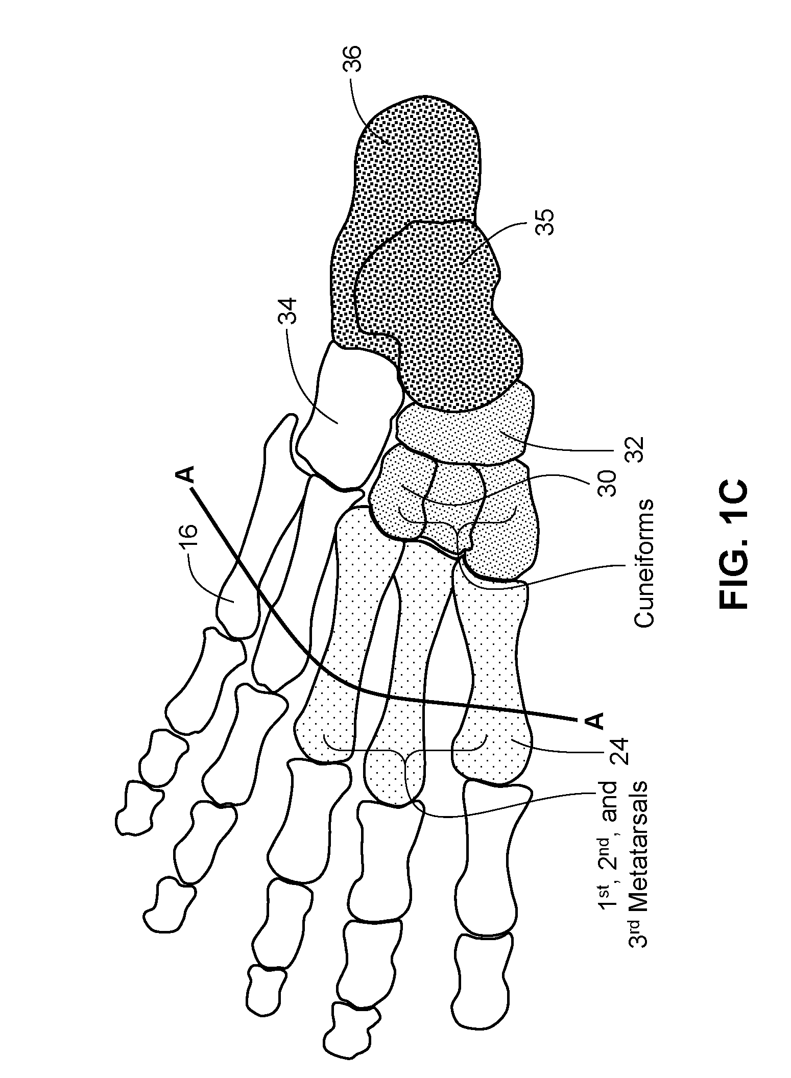
A method for selecting size of an orthotic for a foot is described, where the method comprises collecting certain measurements for a foot, such as a length l1 corresponding to a distance from a proximal point of the heel to a base of a metatarsal head and, optionally, a width w corresponding to a distance from the medial edge of the foot at approximately the base of the first metatarsal head to the lateral edge of the foot at approximately the base of the fifth metatarsal head, and, optionally, a height h corresponding to the height of the lateral foot arch relative to ground. The height h is measured, in some cases, with the foot in an adjusted or restored condition. The measurements are used to recommend or to select a size of an orthotic product.

Description

CROSS-REFERENCE TO RELATED APPLICATIONS[0001]This application claims the benefit of U.S. Provisional Application No. 62 / 189,620, filed Jul. 7, 2015, which is incorporated by reference herein.TECHNICAL FIELD[0002]The subject matter described herein relates to a method for sizing an orthotic device for a foot, a scheme for sizing orthotic devices and a method for determining a correctly sized foot orthotic.BACKGROUND[0003]It has been historically believed that the human foot differs substantially when comparing the feet of individuals, and that a single individual can have significant differences between their right and left feet. These differences have to date resulted in a number of possibilities when trying to classify and categorize human feet into groups in order to aid in the diagnosis and treatment of various pedal and postural conditions and diseases. Early prior art methods for classifying foot types grouped feet according to specific characteristics, such as the type of medi...

Claims


Application Information

Patent Timeline
Patent Type & Authority Applications(United States)
IPC IPC(8): A61B5/107
CPCA61B5/1072A61B5/1074A43B7/142A43B7/28A43D1/02
Inventor LATTERMAN, SUE ANN
Owner LATTERMAN SUE ANN
Why Eureka
Try Eureka