

Orthoris having a particular relief
A raised part, orthopedic technology, applied in insoles, medical science, clothing, etc., can solve problems such as high cost
- Summary
- Abstract
- Description
- Claims
- Application Information
AI Technical Summary
Problems solved by technology
Method used
Image

Examples
Embodiment Construction
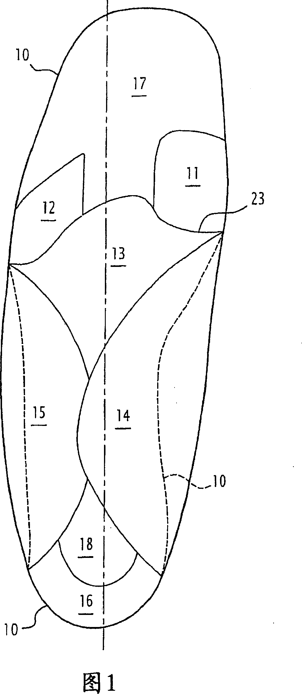
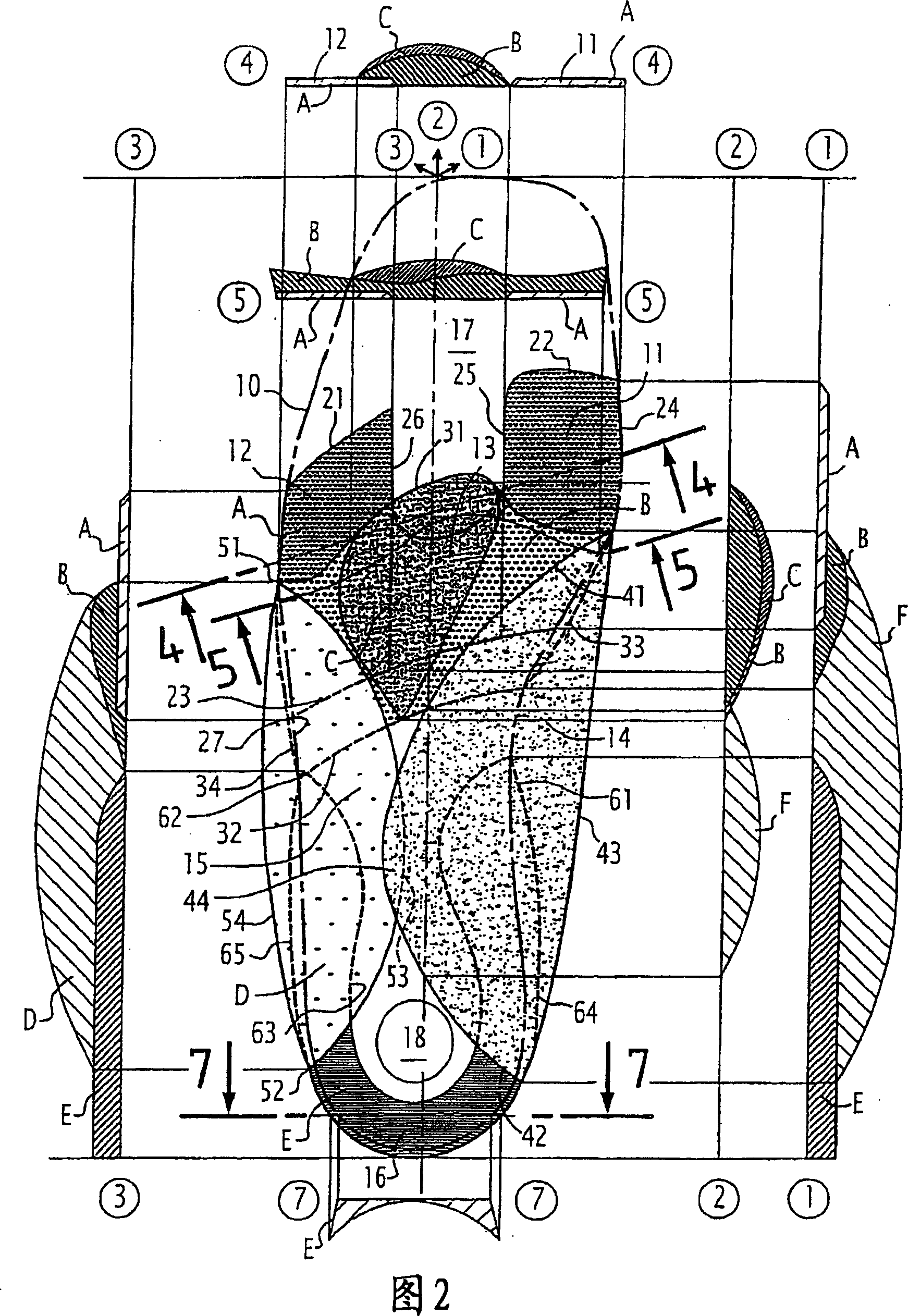
[0024] [24] The plantar orthopedic pad shown in FIG. 1 has a base 10 at its lower part, the base being cut from a thick sheet of flat material, for example, and forming a flat first layer. Some areas are arranged protrudingly on the base, the areas are the inferior metatarsal head area 11 of the first metatarsal, the inferior metatarsal head area 12 of the fourth and fifth metatarsals, and a posterior metatarsal head space area or posterior. Metatarsal head support area 13, an inner half-dome area 14, an outer half-dome area 15, and a heel ring 16.
[0025] [25] According to the present invention, the arrangement shown in Figure 1 determines the contour lines of different regions, of course these regions may vary in their width or length. The length and / or width of the area can preferably be changed within a limit of ±10%, and preferably within a limit of ±7%, relative to the dimensions appearing in the figure, these dimensions being proportional to the size of the orthopedic pad....
PUM
 Abstract
Description
Claims
Application Information