Anchored RF ablation device for the destruction of tissue masses

a tissue mass and ablation device technology, applied in the direction of instruments, prostheses, program control, etc., can solve the problems of difficult piercing of uterine fibroid tissues, extremely time-consuming procedure, and ineffective piercing of uterine stylets, so as to reduce recovery time

Active Publication Date: 2007-01-04
ACESSA HEALTH INC +1
View PDF99 Cites 110 Cited by
  • Summary
  • Abstract
  • Description
  • Claims
  • Application Information

AI Technical Summary

Benefits of technology

[0044] As compared to a conventional hysterectomy, the present invention is directed to a device for the treatment of uterine fibroids and other tissue masses that meets the needs of women by conserving the uterus and reducing recovery time from 6-8 weeks to 3-10 days.

Problems solved by technology

More particularly, it has been discovered that uterine fibroid tissues tend to be difficult to pierce because, unlike other types of tumors, uterine fibroids are comprised of relatively hard muscle-like tissues and the curved stylets tend to deform during deployment.
They are thus not very effective in piercing a uterine stylet.
While the iterative advancement of the stylets, punctuated by relatively long periods of time during which advancement cannot be implemented and the surgeon must wait for the desired degree of deterioration of the tissue into which the antennae will next be advanced, will work to effectively and minimally-invasively ablate a uterine fibroid, the procedure is extremely time-consuming compared to a procedure in which antennae may be fully deployed and radiation applied to a large volume of a uterine fibroid during a single application of RF energy.
Accordingly, while the above procedure has seen some implementation, the time necessary for the procedure has made it relatively expensive and thus it is not available to many individuals.
Moreover, the skill required for the performance of the procedure is relatively high, and thus few doctors are able to perform the procedure.
Proliferation of this approach is not likely in view of the steep learning curve and the small number of individuals competent to perform this procedure.

Method used


Image

  • Anchored RF ablation device for the destruction of tissue masses
  • Anchored RF ablation device for the destruction of tissue masses
  • Anchored RF ablation device for the destruction of tissue masses

Examples


Embodiment Construction

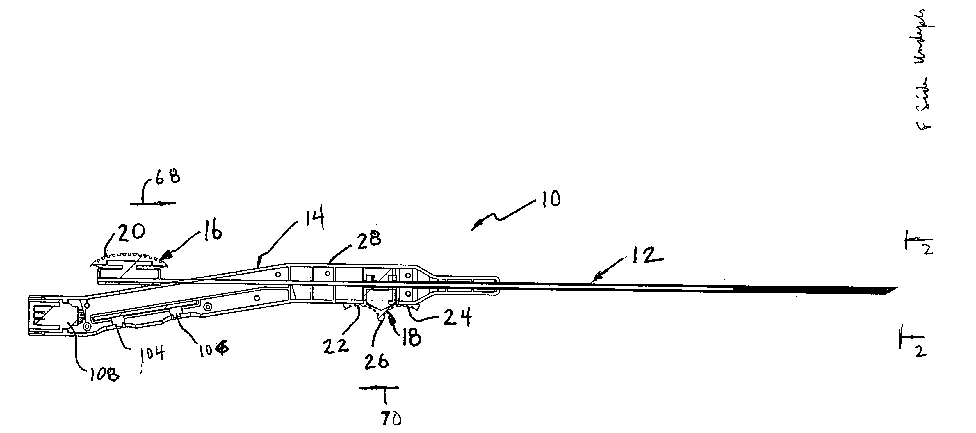
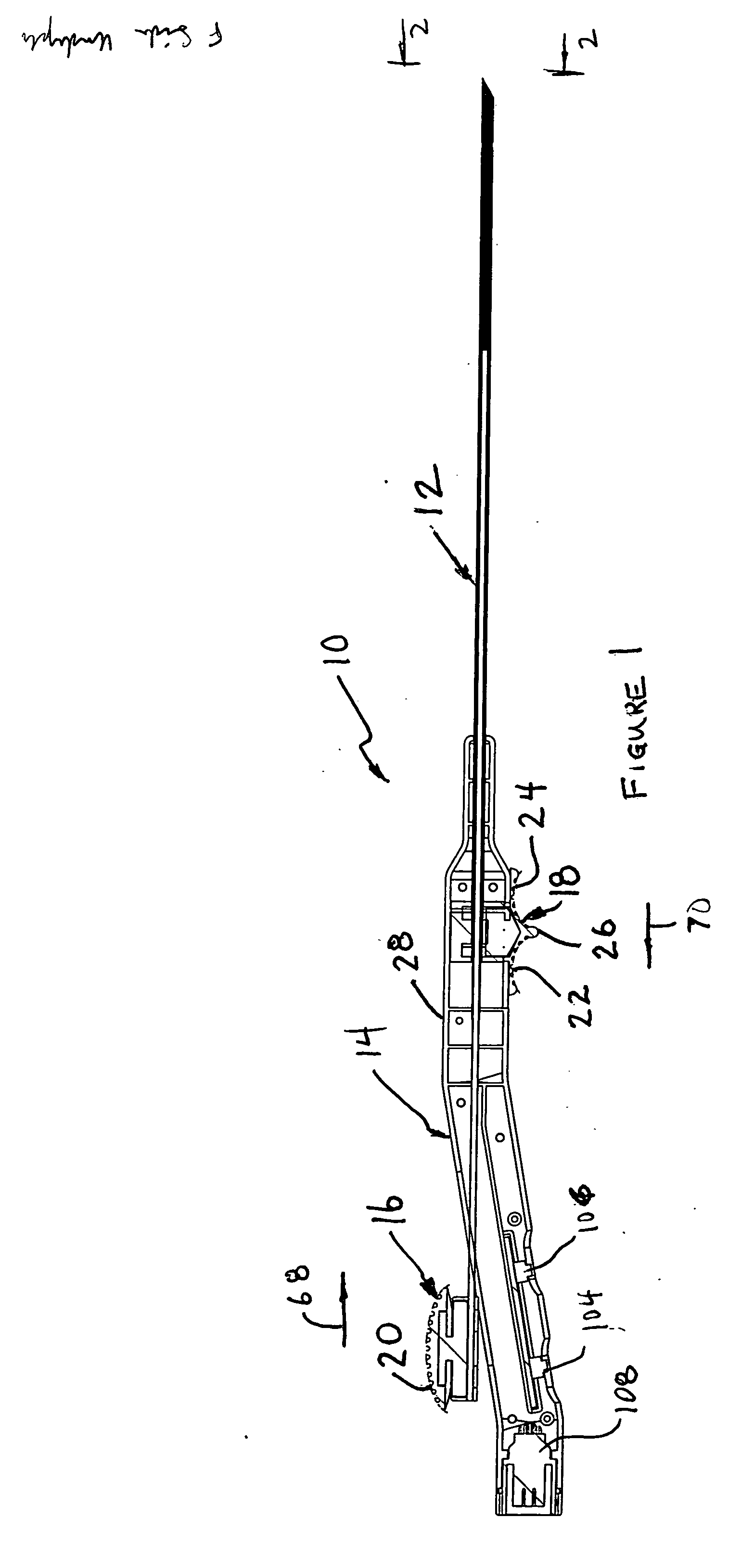
[0079] Referring to FIG. 1, an ablation instrument 10 constructed in accordance with the present invention is illustrated. Instrument 10 comprises a catheter portion 12 and a handle portion 14. Ablation instrument 10 is illustrated with one of the two mating handle halves removed and partially in cross section, in order to reveal its internal parts and workings in connection with the following description.

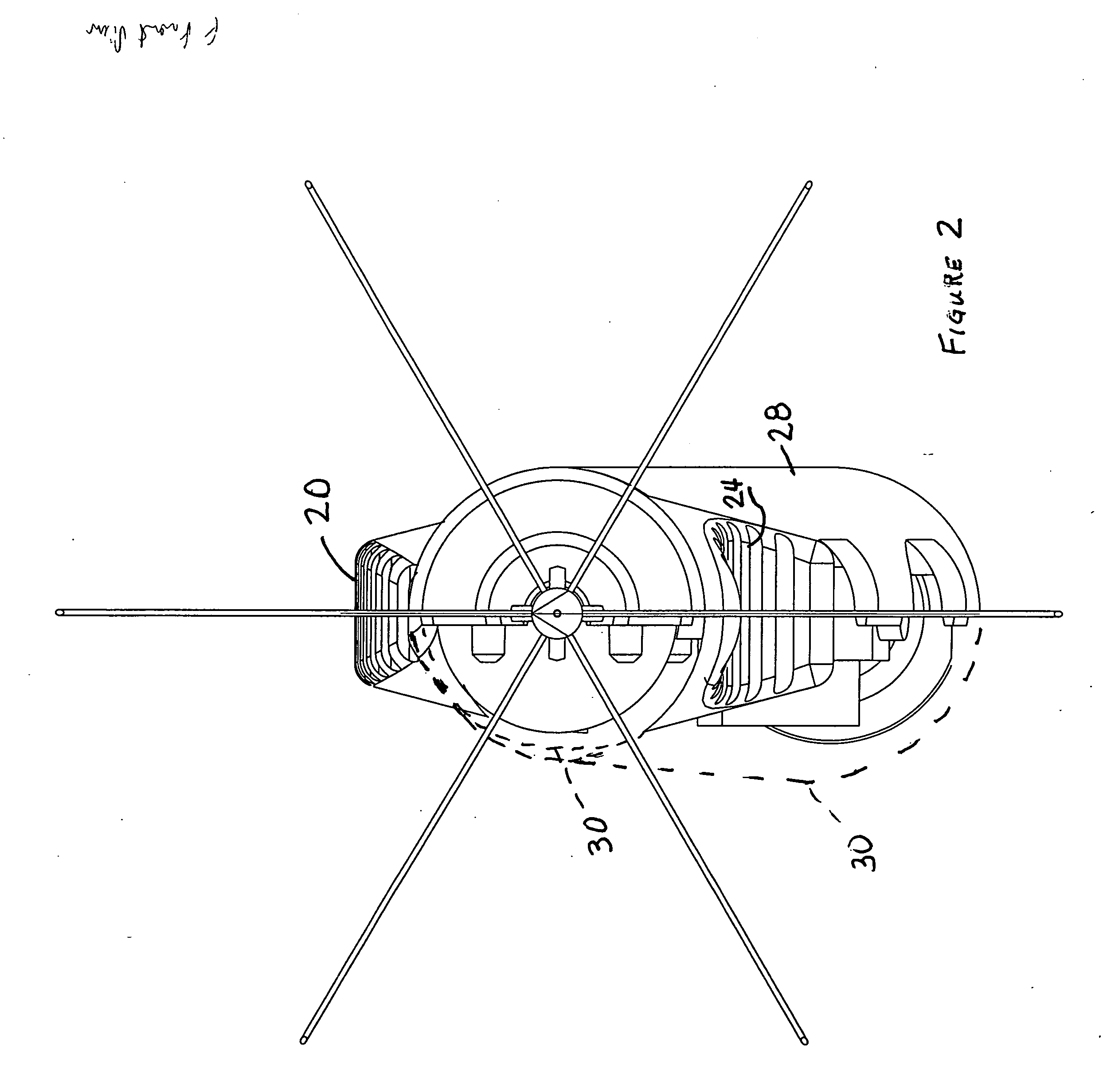
[0080] Referring to FIGS. 1 and 2, the inventive ablation instrument 10 is illustrated in the fully retracted position suitable for advancement of catheter portion 12 into tissue, for example, tissue to be subjected to ablation by being treated with radiofrequency energy. In this position, the catheter 12 present a simple thin smooth pointed surface well-suited to penetrate healthy tissue while doing minimal damage. At the same time, the sharpness of the point and the relatively stiff, though somewhat flexible, nature of catheter 12 enables accurate steering of the point and contr...


PUM


Abstract

The inventive ablation element comprises an elongated cannula having a proximal end and a distal end. The cannula defines an internal lumen within the cannula and a cannula axis. A plurality of conductors contained within the lumen, each of the conductors has a proximal end proximate the proximal end of the cannula, and a distal end proximate the distal end of the cannula. A plurality of ablation stylets each has a proximal end and a distal end, and each coupled at the respective proximal end of the stylet to the distal end of a respective conductor, the stylets comprise a deflectable material, the conductors together with their respective stylets being mounted for axial movement. A trocar point defined proximate the distal end of the cannula. A deflection surface positioned between the trocar point and the proximal end of the cannula, the deflection surface being configured and positioned to deflect, in response to axial movement of the stylets in a direction from the proximate end of the cannula to the distal end of the cannula, at least some of the stylets laterally with respect to the cannula axis in different directions along substantially straight paths, the paths defining an ablation volume.

Description

CROSS REFERENCE TO RELATED APPLICATION [0001] This application is a continuation in part of U.S. patent application Ser. No. 11 / 173,928, entitled Radio Frequency Ablation Device for the Destruction of Tissue Masses filed on Jul. 1, 2005, the disclosure of which is incorporated by reference. BACKGROUND [0002] In the United States, approximately 230,000 women have hysterectomies annually. The primary reason for performing a hysterectomy is the presence of uterine fibroids. These fibroids grow in the wall of the uterus and may range in size up to several inches across. In the United States alone, there are more than six million women with uterine fibroid symptoms who prefer to suffer, rather than endure the risks and inconveniences associated with major surgery, especially a major surgery that results in infertility. Outside of the United States, the situation is much the same, with millions of women suffering with fibroids in need of a safe alternative to hysterectomy. [0003] Recently...

Claims


Application Information

Patent Timeline
Patent Type & Authority Applications(United States)
IPC IPC(8): G06F9/44
CPCA61B18/1477A61B18/1815A61B2018/00577A61B2018/00702A61B2018/00738A61B2018/00761A61B2018/00791A61B2018/1425A61B2018/143A61B2018/1432A61B2018/1475A61B2018/1869A61B2018/0094A61B2018/00559A61B2018/00214A61B2017/3454A61B2018/1467A61B18/18A61B18/14A61B17/3421A61B2018/1405A61B2018/00273
Inventor EPSTEIN, GORDONLEE, BRUCECOHEN, JEFFREY M.HAGMANN, ADAMSPERO, RICHARD
Owner ACESSA HEALTH INC
Why Eureka
Try Eureka