Linear Repeating Firearm With Assisted Ejection

Active Publication Date: 2017-02-16
VERNEY CARRON SA
View PDF2 Cites 7 Cited by
  • Summary
  • Abstract
  • Description
  • Claims
  • Application Information

AI Technical Summary

Problems solved by technology

This is not the case with a semi-automatic firearm in which the magazine is tilting and non-movable and whose capacity is generally limited to a maximum of two cartridges depending on the laws.

Method used


Image

  • Linear Repeating Firearm With Assisted Ejection
  • Linear Repeating Firearm With Assisted Ejection

Examples


Embodiment Construction

[0022]As stated, the invention applies to any firearm type of the repeating weapon type, whatever the caliber.

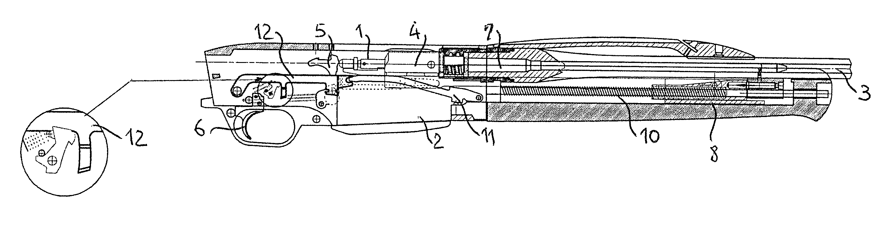
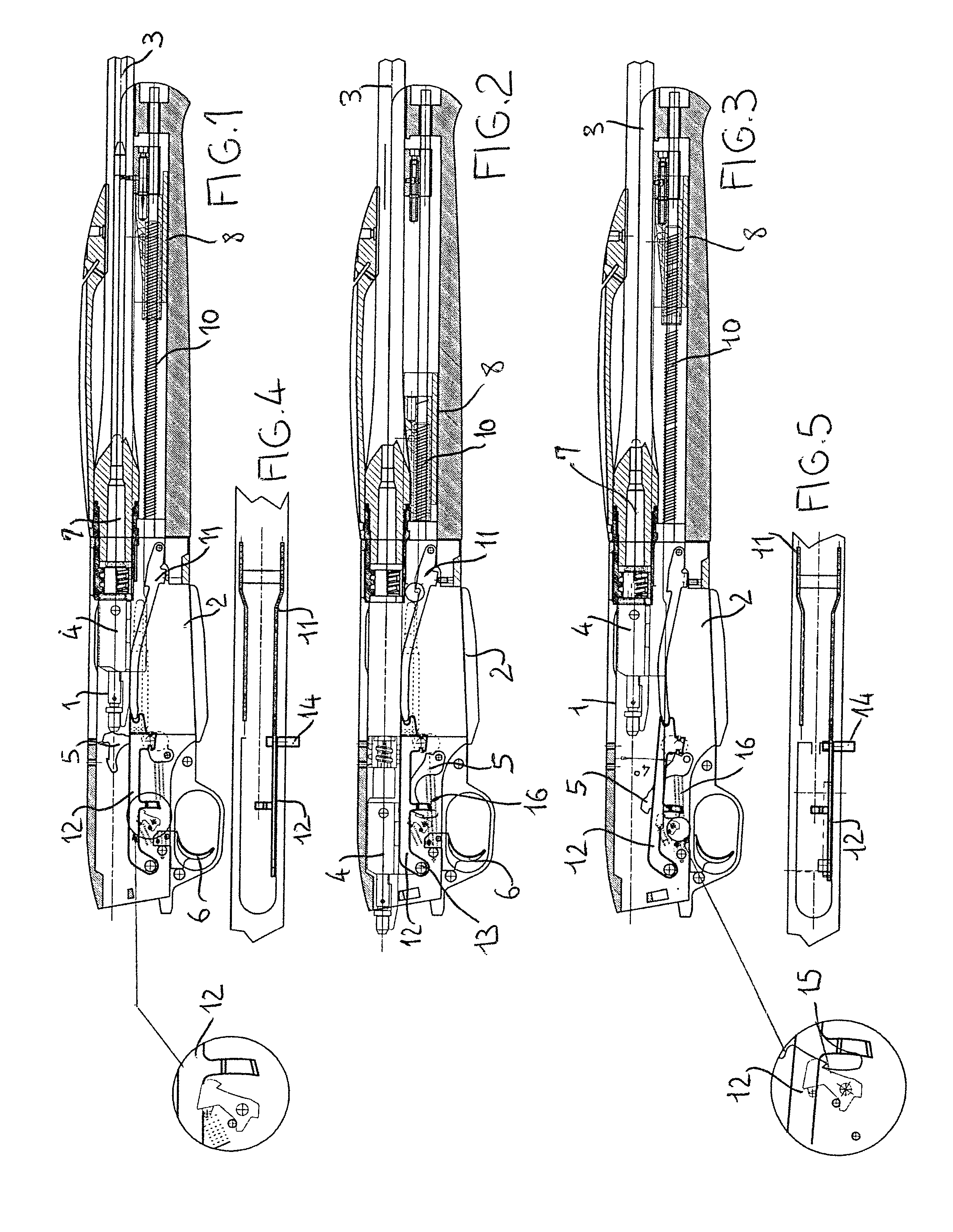
[0023]This type of weapon is well known for a skilled person and may have various embodiments. Essentially, this type of weapon includes a butt, not shown, a breech casing (1), a magazine (2) and a barrel (3). The breech casing (1) is a movable assembly (4) consisting essentially of a stopper, a latch and a striker, which is struck by the tilting effect of a hammer (5) controlled by a trigger (6).

[0024]According to the invention, the arming of the movable assembly (4) is effected by means capable of recovering the energy resulting from the pressure exerted during the firing of an ammunition (7). This energy can be recovered either by inertia or by a gas operated system, or by recoil of the barrel, as with the firearms of the semi-automatic weapon type. This energy recovery allows therefore the displacement of the movable assembly (4) against a resilient return member (10). F...


PUM


Abstract

A linear repeating firearm, with assisted ejection, including: a mechanism capable of recovering the energy resulting from pressure exerted when firing a round of ammunition with a view to moving a mobile assembly against an elastic return member and including a stopper, a latch and a striker cooperating with a hammer controlled by a trigger. A locking mechanism is provided at the rear of the mobile assembly, to lock the mobile assembly in the compressed position of the return spring, after each shot. A manually actuatable unlocking assembly is capable of acting on the locking mechanism to release the mobile assembly and allow the assisted return of the assembly with a view to reloading.

Description

FIELD OF THE INVENTION[0001]The invention relates to the technical field of firearms.[0002]The invention relates more particularly to a manual repeating firearm of any caliber, particularly of the linear arming type.BACKGROUND OF THE INVENTION[0003]In a perfectly known manner for a skilled person, this type of weapon includes a movable assembly mounted in a breech casing that comprises the weapon. This movable assembly comprises, essentially, a stopper, a latch and a striker, which can be struck by the tilting effect of a hammer controlled by a trigger, against a return spring. The rearmament and the ejection are thus performed according to a reciprocating movement of the movable assembly which cooperates with an actuating member positioned for example at the front of the weapon, being mounted to slide freely within the barrel, or with an actuating member positioned on the movable assembly.[0004]Arming the percussion system is thus effected in a manual manner, which is not the case ...

Claims


Application Information

Patent Timeline
Patent Type & Authority Applications(United States)
IPC IPC(8): F41A3/26F41A5/18
CPCF41A5/18F41A3/26F41A17/32
Inventor VERNEY-CARRON, PIERRE
Owner VERNEY CARRON SA
Why Eureka
Try Eureka