Lifting Holder Structure

a technology for lifting holder and related components, which is applied in the field of lifting holder structures, can solve the problems that the precision of related components of the lifting holder cannot be controlled well, and achieve the effect of improving the precision of the workpiece of the related components

Inactive Publication Date: 2017-02-23
CHERN SHING TOP
View PDF16 Cites 25 Cited by
  • Summary
  • Abstract
  • Description
  • Claims
  • Application Information

AI Technical Summary

Benefits of technology

[0011]The threaded section of the second screwing post has outer threads for screwing with inner threads defined in the hollow fitting section of the second screwing post, and the threaded section of the second screwing post is rotatably connected with the first screwi

Problems solved by technology

However, a workpiece precision of related componen

Method used


Image

  • Lifting Holder Structure
  • Lifting Holder Structure
  • Lifting Holder Structure

Examples


Embodiment Construction

[0020]The present invention will be clearer from the following description when viewed together with the accompanying drawings, which show, for purpose of illustrations only, the preferred embodiment in accordance with the present invention.

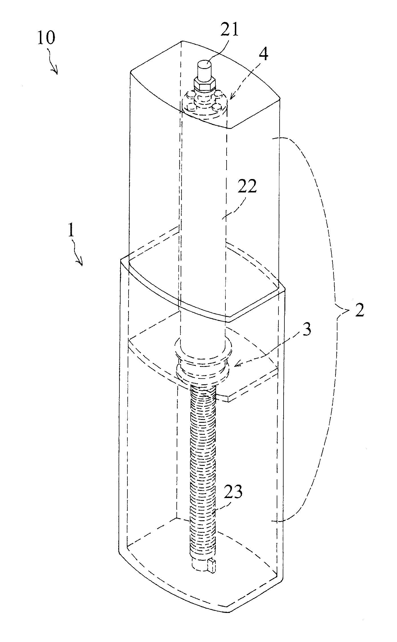
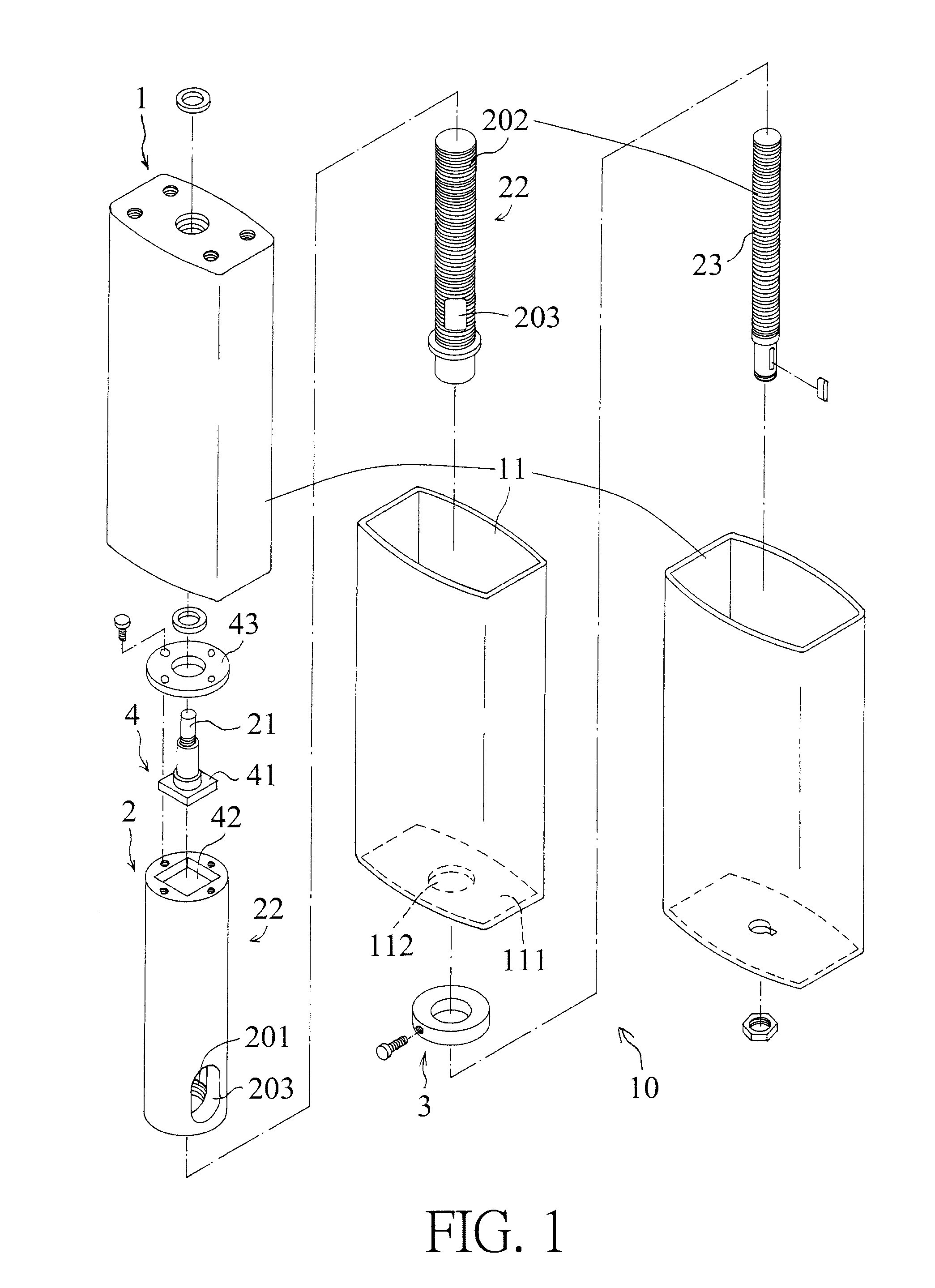
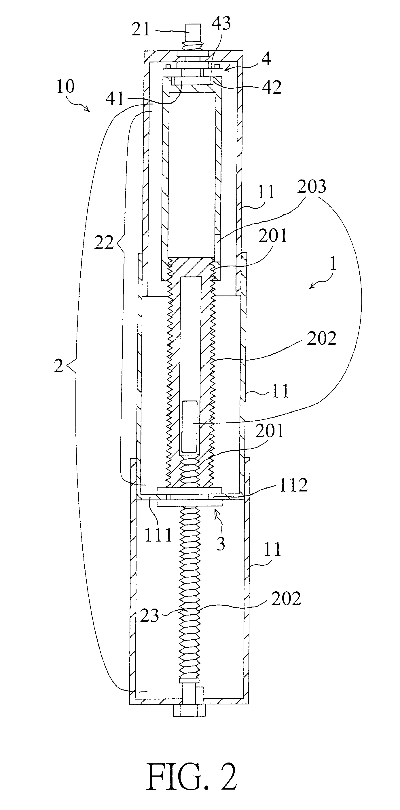
[0021]A lifting holder structure according to a preferred embodiment of the present invention comprises: a base 1 and a moving rod 2 (as shown in FIG. 1), wherein the base 1 includes plural fitting sleeves 11 which are fitted together, and the moving rod 2 includes a first screwing post 23 arranged on a bottom end thereof and fitted into a second screwing post 22 via a lowermost of the plural fitting sleeves 11, wherein the second screwing post 22 has a hollow fitting section and a threaded section below the hollow fitting section, wherein a part of the hollow fitting section of the second screwing post 22 is screwed in an uppermost of the plural fitting sleeves 11 of the base 1, and a driving post 21 rotatably connects with a top end of the uppe...


PUM


Abstract

A lifting holder structure contains a base and a moving rod, and the base includes plural fitting sleeves which are fitted together, the moving rod includes a first screwing post arranged on a bottom end thereof and fitted into a second screwing post via a lowermost of the plural fitting sleeves. The second screwing post and the plural fitting sleeves are fixed via an interstitial connecting structure, and a top of the second screwing post is limited by a driving post within an angle range and is driven by an angular coupling structure, such that the driving post rotates to drive the second screwing post and a first screwing post to change a pitch stroke, thus moving a lifting holder vertically.

Description

BACKGROUND OF THE INVENTION[0001]Field of the Invention[0002]The present invention relates to a lifting holder structure contains a base and a moving rod in which a second screwing post is fitted, wherein the second screwing post and plural fitting sleeves are fixed via an interstitial connecting structure, and a top of the second screwing post is limited by a driving post within an angle range and is driven by an angular coupling structure, such that the driving post rotates to drive the second screwing post and a first screwing post to change a pitch stroke, thus moving a lifting holder vertically and swinging the second screwing post smoothly in a predetermined margin.[0003]Description of the Prior Art[0004]A conventional lifting holder lifts and descends objects (such as a desk) based on a desired height, wherein a threaded structure is arranged in the lifting holder to adjust a height of the objects except for the desk.[0005]For example, the lifting holder is fixed on the desk ...

Claims


Application Information

Patent Timeline
IPC IPC(8): F16M11/26A47B9/04
CPCF16M11/26A47B2200/002A47B2009/043A47B9/04F16M11/18
Inventor HSIAO, HSUEH-SHENG
Owner CHERN SHING TOP
Why Eureka
Try Eureka