Optical fiber

a technology of optical fiber and optical fiber, applied in the field of optical fiber, can solve the problems of osnr being lower, and achieve the effect of excellent osnr and communication

Active Publication Date: 2017-03-16
SUMITOMO ELECTRIC IND LTD
View PDF2 Cites 1 Cited by
  • Summary
  • Abstract
  • Description
  • Claims
  • Application Information

AI Technical Summary

Benefits of technology

[0014]By using the optical fiber according to the present invention as an optical transmission path, optical communication can be performed with an excellent OSNR.

Problems solved by technology

However, in an optical fiber with an increased effective area, the confinement of propagation light (fundamental-mode light) to a core weakens and a micro-bend loss tends to increase, ultimately causing the OSNR to become lower.

Method used


Image

  • Optical fiber
  • Optical fiber
  • Optical fiber

Examples


Embodiment Construction

[0023]An embodiment of the present invention will be described in detail below with reference to the appended drawings. The present invention is not to be limited to the following examples and is intended to include all modifications that are indicated by the scope of the claims and that have meanings equivalent to and within the scope of the claims.

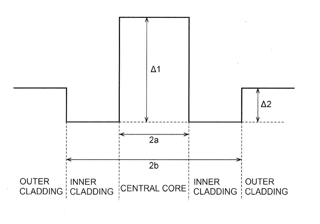
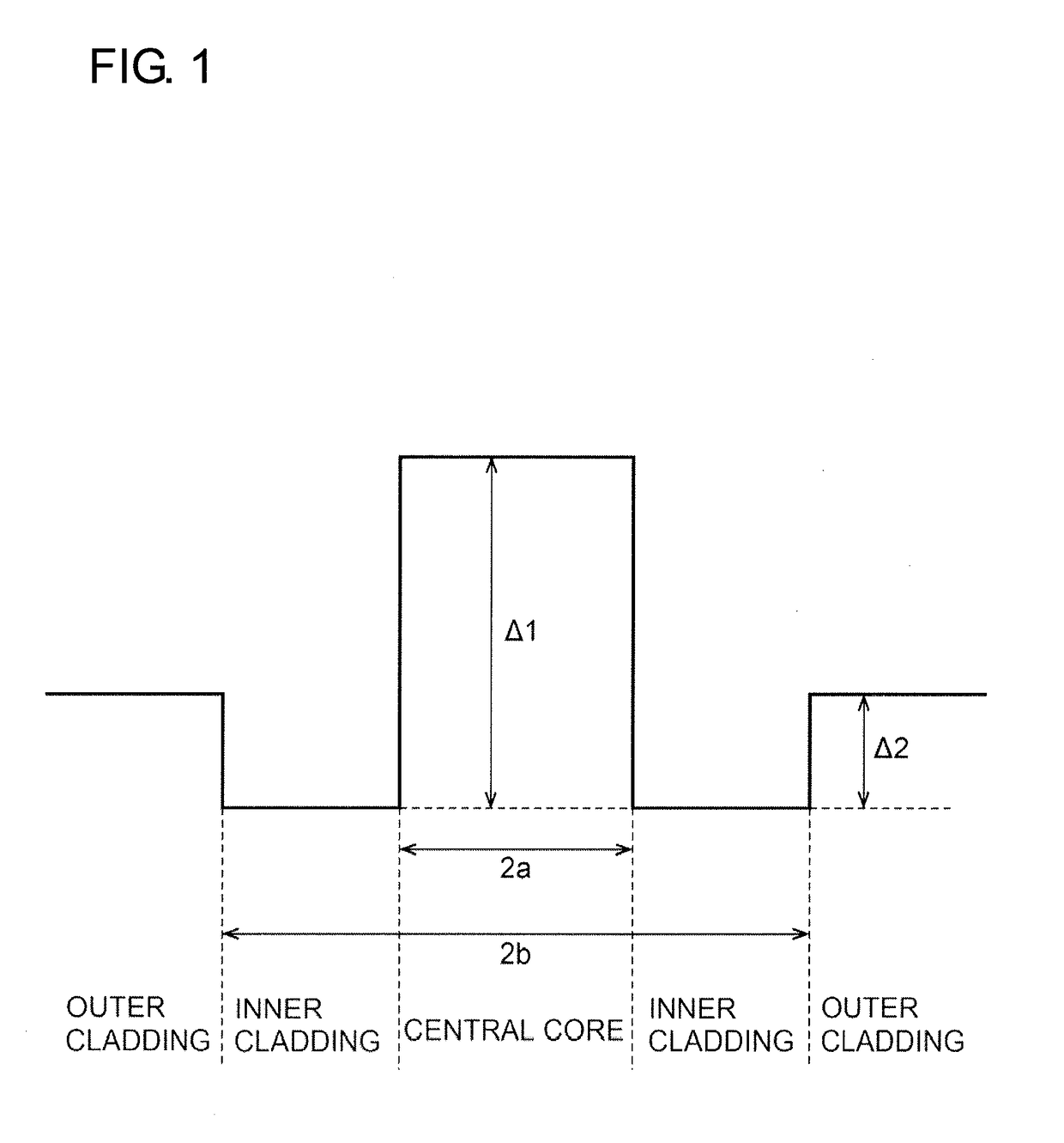
[0024]FIG. 1 schematically illustrates refractive-index distribution of an optical fiber according to an embodiment of the present invention. The optical fiber according to this embodiment has a core, inner cladding surrounding the core, and outer cladding surrounding the inner cladding. The refractive index of the inner cladding is smaller than the refractive index of the core. The refractive index of the outer cladding is smaller than the refractive index of the core and is larger than the refractive index of the inner cladding. The diameter of the core is denoted by 2a, and the outer diameter of the inner cladding is denoted by 2b. Wi...


PUM


Abstract

Provided is an optical fiber having W-shaped refractive-index distribution and in which a micro-bend loss in an actual usage waveband is reduced. The optical fiber includes a core, inner cladding that surrounds the core and has a refractive index smaller than a refractive index of the core, and outer cladding that surrounds the inner cladding and has a refractive index smaller than the refractive index of the core and larger than the refractive index of the inner cladding. When a coupling coefficient between a fundamental mode and a cladding mode is denoted by C01-CL, a coupling coefficient between the fundamental mode and a higher-order mode is denoted by C01-11, and a coupling coefficient between the higher-order mode and the cladding mode is denoted by C11-CL, Ctotal defined as Ctotal=C01-CL+C01-11C11-CL has a minimum value at a wavelength ranging between 1520 nm and 1630 nm.

Description

CROSS-REFERENCE TO RELATED APPLICATIONS[0001]The present application is a continuation application of International Application No. PCT / JP2015 / 065976, filed Jun. 3, 2015, which claims priority to Japanese[0002]Patent Application No. 2014-116529, filed Jun. 5, 2014. The contents of these applications are incorporated herein by reference in their entirety.BACKGROUND OF THE INVENTION[0003]1. Field of the Invention[0004]The present invention relates to optical fibers.[0005]2. Technical Background[0006]In optical communication systems, optical-fiber transmission paths are used as optical transmission paths that transmit signal light. In signal light transmission (i.e., digital coherent transmission in particular), it is desirable that the OSNR (optical signal-to-noise ratio) be improved. In order to achieve this, it is required to reduce attenuation and nonlinearity of an optical fiber. In order to reduce nonlinearity of an optical fiber, it is effective to increase the effective area of...

Claims


Application Information

Patent Timeline
Patent Type & Authority Applications(United States)
IPC IPC(8): G02B6/02G02B6/036
CPCG02B6/03633G02B6/02019C03B2203/22C03B2203/23G02B6/03611G02B6/03627G02B6/036
Inventor KAWAGUCHI, YUKIYAMAMOTO, YOSHINORIHIRANO, MASAAKI
Owner SUMITOMO ELECTRIC IND LTD
Why Eureka
Try Eureka