Vaporizer With Electronically Heated Nail

Inactive Publication Date: 2017-03-23
CLOUD V ENTERPRISES
View PDF12 Cites 48 Cited by
  • Summary
  • Abstract
  • Description
  • Claims
  • Application Information

AI Technical Summary

Benefits of technology

[0010]The pan is easily and conveniently attached to, and detached from, the battery housing of the vaporizer. When the pan is attached to the battery housing, it is also in electrical contact with the battery. The electrical power from the battery, is controlled by a microprocessor or similar controller. Preferably, the pan is constructed from a heat conductive material at locations where

Problems solved by technology

Vaporizers in which the solid, liquid or suspension material sought to be vaporized is placed onto a pre-heated surface, however, have remained bulky, expensive, dangerous and inconvenient.
While this sort of apparatus provides for creative aesthetics, it also has significant drawbacks.
User of a torch 9 to heat a slide 7 is inherently dangerous because it employs a combustible hydrocarbon and results in an exposed and extremely hot slide 7, usually made of a heat conductible metal.
Some prior art vaporizers include an alternative heating source, such as an electronic heat device that connects to the slide 7, however, they are generally bulky and expensive.
The size of the vaporizer 3,

Method used


Image

  • Vaporizer With Electronically Heated Nail
  • Vaporizer With Electronically Heated Nail
  • Vaporizer With Electronically Heated Nail

Examples


Embodiment Construction

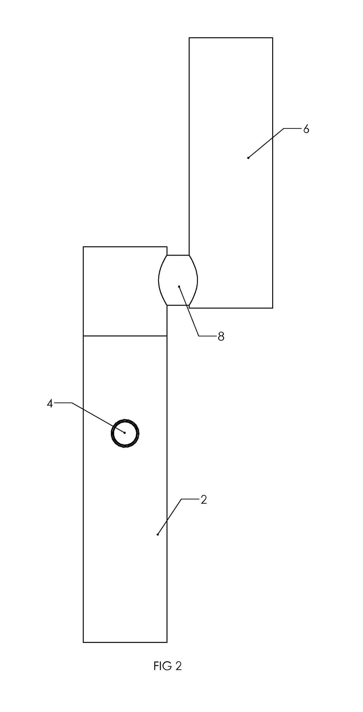
[0017]As depicted in FIG. 2, the preferred embodiment compact vaporizer includes a battery housed within a battery casing 2 and a mouthpiece 6. Disposed on the battery casing is a large button 4 that enables a user to activate a heating element (discussed below). Connection cylinder 8 connects the mouthpiece 6 to battery casing 2, and provides for an air pathway from the mouthpiece 6 to the vaporized substance (discussed below). Disposed on the bottom of the battery casing 2 is a charging connection that enables the battery to be recharged through connection to an electrical source. The charging connection may be of any type, but USB is preferred because of its current universality.

[0018]Turning to FIG. 3, disposed at the top of the mouthpiece 6 is an inhalation opening 11. Through the inhalation opening 11, the user can inhale the substance vaporized through the operation of the compact vaporizer as described herein. Disposed at the top of the battery casing, is a pan 10. As discus...


PUM


Abstract

A vaporizer comprising a mouthpiece and battery. The mouthpiece preferably includes an upper chamber and a lower chamber separated by a small distance and providing an air pathway through the length of the mouthpiece, and a cooling liquid surrounding a portion of the lower chamber. Electrically connected to the battery is a pan that includes a heating element that heats the top surface of the pan to a desired temperature for vaporizing, but not combusting, a substance desired to be inhaled. A pan protector, made of an insulating material, surrounds the sides of the pan to prevent injury to a user. The vaporizer further includes a controller for ensuring that the pan is heated only to a pre-selected temperature sufficient to vaporize, but not combust, the chosen substance.

Description

BACKGROUND OF THE INVENTION[0001]1. Field of the Invention[0002]The present invention relates generally to the field of vaporizers used to heat solids, liquid and suspensions, such as waxes and oils, for inhalation by a user.[0003]2. Prior Art[0004]Vaporizers, including electronic cigarettes, have become increasingly popular over the past ten years. As consumers have become more aware of the health consequences of inhaling smoke produced by combusting tobacco and other substances, vaporizers have become a healthier alternative to cigarettes, cigars, pipes and other smoking implements. While some vaporizers are large and bulky—sometimes intended to mimic the aesthetic look of a bookah—most vaporizers are small enough to fit into a user's pocket or purse for convenience.[0005]Vaporizers in which the solid, liquid or suspension material sought to be vaporized is placed onto a pre-heated surface, however, have remained bulky, expensive, dangerous and inconvenient. The drawbacks of such ...

Claims


Application Information

Patent Timeline
IPC IPC(8): A24F47/00A24F40/42A24F40/46A24F40/50
CPCA24F47/008A24F1/30A24F40/46A24F40/50A24F40/42
Inventor EKSOUZIAN, VAHAN
Owner CLOUD V ENTERPRISES
Why Eureka
Try Eureka