Map display device, navigation device and map display method
a map display and navigation device technology, applied in navigation instruments, instruments, transportation and packaging, etc., can solve problems such as inability to inform users dynamically
- Summary
- Abstract
- Description
- Claims
- Application Information
AI Technical Summary
Benefits of technology
Problems solved by technology
Method used
Image

Examples
embodiment 1
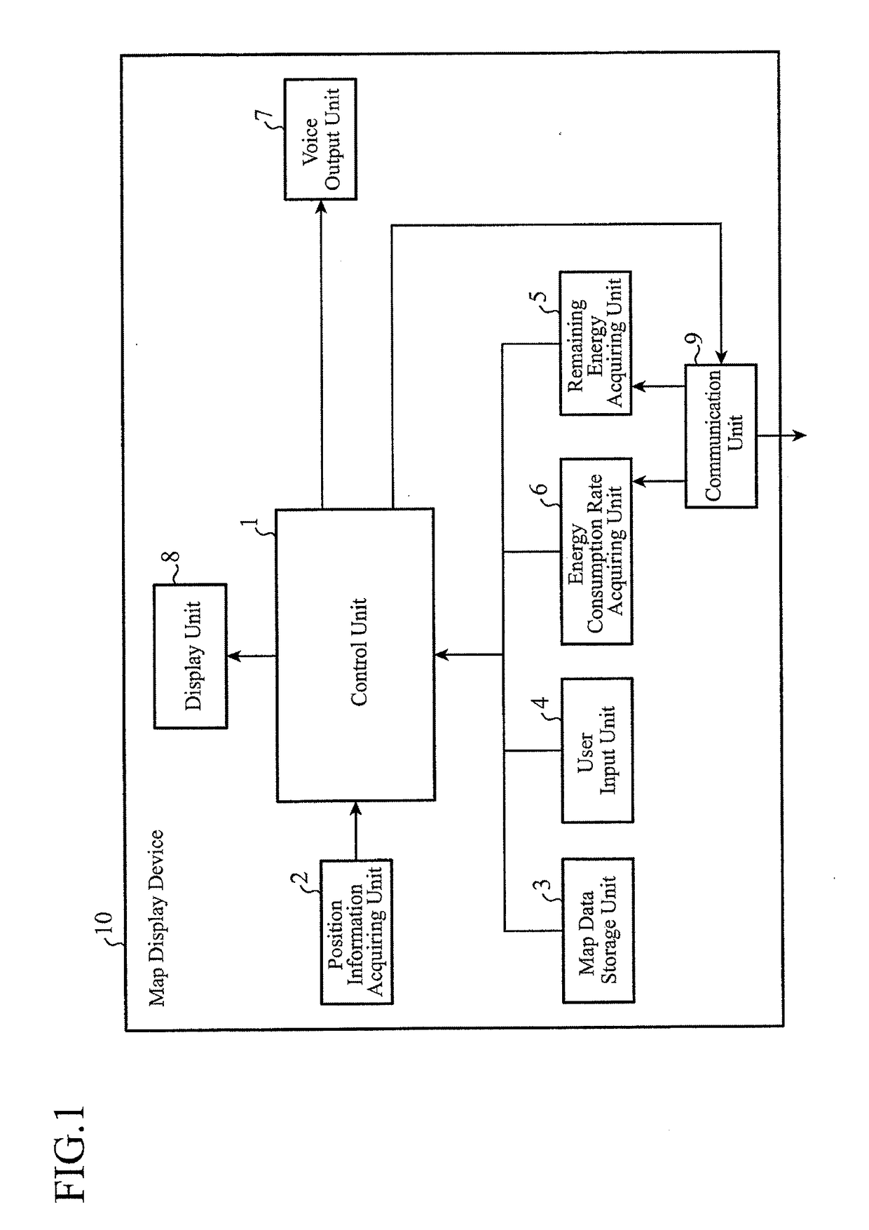
[0037]FIG. 1 is a block diagram showing a configuration of a map display device of an embodiment 1. In FIG. 1, the map display device 10 of the embodiment 1 comprises a control unit 1, a position information acquiring unit 2, a map data storage unit 3, a user input unit 4, a remaining energy acquiring unit 5, an energy consumption rate acquiring unit 6, a voice output unit 7, a display unit 8 and a communication unit 9. Although the map display device 10 is applicable to various mobile units, the following description will be made by way of example applied to a vehicle.
[0038]The control unit 1 is generally composed of a CPU, a memory and the like as an embedded system. The position information acquiring unit 2 obtains the position information of its own vehicle from GPS information supplied from an external device (not shown) or from various driving information such as vehicle speed information and steering angle of the wheel. The map data storage unit 3 stores map data for a naviga...
embodiment 2
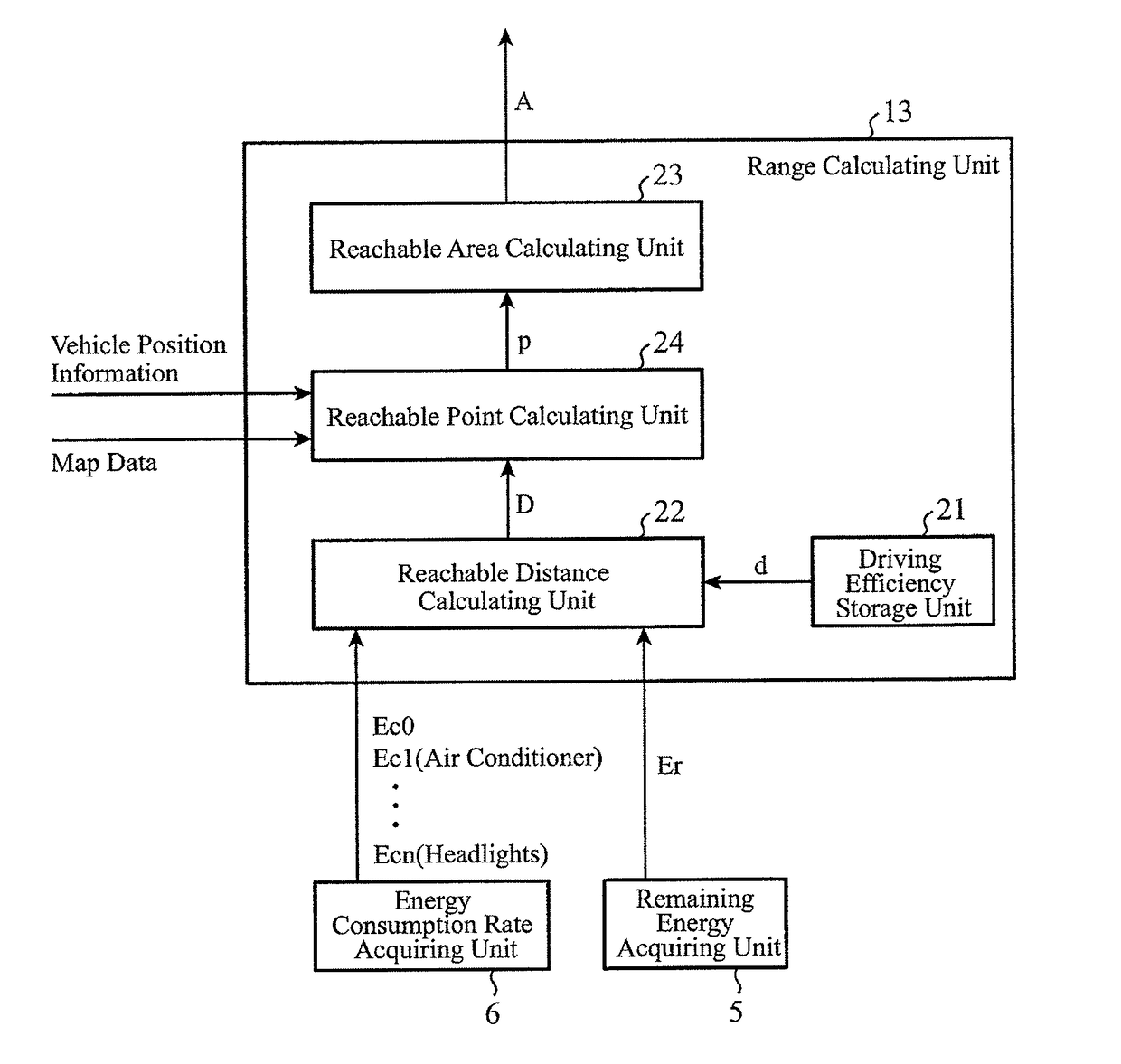
[0062]The present embodiment 2 shows a configuration that calculates a reachable point along amain road from the vehicle position according to the reachable distance D shown in the foregoing embodiment 1.
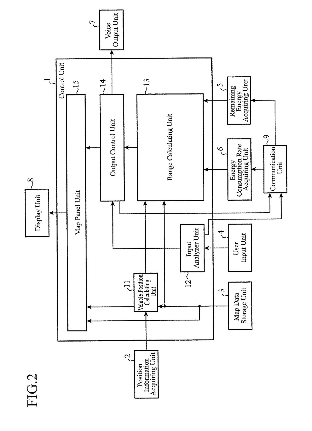
[0063]FIG. 7 is a block diagram showing a configuration of a map display device of the embodiment 2. The map display device 10 of the embodiment 2 further comprises in the range calculating unit 13 a reachable point calculating unit 24 for obtaining a reachable point from the reachable distance D the reachable distance calculating unit 22 calculates in addition to the configuration described in the foregoing embodiment 1 with reference to FIG. 1-FIG. 3. Incidentally, in the following description, the same or like components to those of the map display device 10 of the embodiment 1 are designated by the same reference numerals, and their description will be omitted or simplified.
[0064]The reachable point calculating unit 24 calculates a reachable point p from the reachable distance D...
embodiment 3
[0082]FIG. 13 is a block diagram showing a configuration of a range calculating unit of a map display device of the embodiment 3. The range calculating unit 13 of the present embodiment 3 has, in addition to the configuration described in the foregoing embodiment 1 with reference to FIG. 3, a sunshine information acquiring unit 25 for acquiring sunset time and sunrise time. Incidentally, in the following description, the same or like components to those of the map display device 10 of the embodiment 1 are designated by the same reference numerals used in the embodiment 1, and their description will be omitted or simplified.
[0083]The sunshine information acquiring unit 25 retains a sunshine database as shown in FIG. 14, for example, obtains the sunset time or sunrise time at the present vehicle position by referring to the sunshine database, and calculates time H1 from the present time to sunset or time H2 from the present time to dawn. FIG. 14(a) is a sunset timetable which shows su...
PUM
 Abstract
Description
Claims
Application Information
 - R&D
- Intellectual Property
- Life Sciences
- Materials
- Tech Scout
- Unparalleled Data Quality
- Higher Quality Content
- 60% Fewer Hallucinations
Browse by: Latest US Patents, China's latest patents, Technical Efficacy Thesaurus, Application Domain, Technology Topic, Popular Technical Reports.
© 2025 PatSnap. All rights reserved.Legal|Privacy policy|Modern Slavery Act Transparency Statement|Sitemap|About US| Contact US: help@patsnap.com