Driving support device

Active Publication Date: 2017-03-30
TOYOTA JIDOSHA KK
View PDF5 Cites 23 Cited by
  • Summary
  • Abstract
  • Description
  • Claims
  • Application Information

AI Technical Summary

Benefits of technology

[0008]The present invention has been made in view of these situations, and a main purpose thereof is to provide a technique in which, in a

Problems solved by technology

However, it is not necessarily the case that a driver can visually recognize all of the speed signs surely, because of

Method used


Image

  • Driving support device
  • Driving support device
  • Driving support device

Examples


Embodiment Construction

[0015]The invention will now be described by reference to the preferred embodiments. This does not intend to limit the scope of the present invention, but to exemplify the invention.

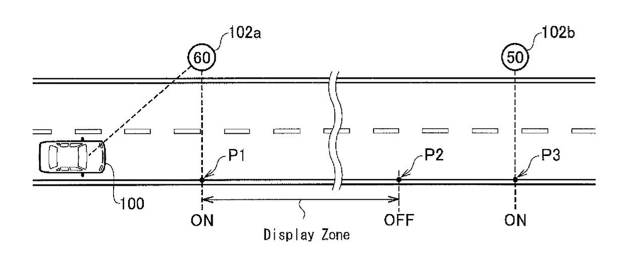
[0016]FIG. 1 is a first schematic view for explaining speed display control. A vehicle 100 has a camera mounted therein. The camera images a speed sign 102. A driving support device (described later) that is mounted in the vehicle 100 acquires information indicating a speed limit from the speed sign 102 by image recognition. Hereinafter, the speed limit acquired from the speed sign 102 is referred to as “main speed information.” In the case of FIG. 1, it is recognized by the image recognition of a speed sign 102a that a speed limit at and after a point P1 is 60 km / h. When the vehicle 100 passes through the point P1, “Speed limit is 60 km / h” is displayed on a meter panel in the vehicle 100. Hereinafter, displaying the main speed information on a display device, such as a meter panel, is referred to as “sp...


PUM


Abstract

A driving support device detects a speed limit by imaging a speed sign indicating the speed limit of a traveling lane. Also, the driving support device continuously acquires attribute information from a car navigation system. The speed limit recognized from a road sign is displayed on a screen mounted in a vehicle. When the speed limit recognized from the road sign is not equal to a speed limit acquired from the car navigation system, a display time of the speed limit is limited. When the attribute information is changed, display of the speed limit is stopped.

Description

BACKGROUND OF THE INVENTION[0001]1. Field of the Invention[0002]The present invention relates to a technique in which a driver is notified of a speed limit by acquiring the speed limit from a road sign, etc.[0003]2. Description of the Related Art[0004]A road sign indicating a speed limit (hereinafter, simply referred to as a “speed sign”) is installed on a road. A driver visually recognizes the speed sign to adjust a vehicle speed. However, it is not necessarily the case that a driver can visually recognize all of the speed signs surely, because of various reasons in which the driver is talking with a fellow passenger, gazing at a car navigation system, and the like.[0005]In Patent Document 1, a speed sign is imaged by a camera such that a speed limit is acquired from the image information. When the speed limit acquired from the camera is displayed, a driver can visually recognize the speed limit even if he or she overlooks the speed sign, and hence safer driving can be achieved.REL...

Claims


Application Information

Patent Timeline
IPC IPC(8): G08G1/0962G06K9/00
CPCG08G1/09623G06K9/00818G08G1/09626G01C21/3492G06V20/582
Inventor FUJIMAKI, YUSUKE
Owner TOYOTA JIDOSHA KK
Why Eureka
Try Eureka