
Impression tray, and method for capturing structures, arrangements or shapes, in particular in the mouth or human body

Inactive Publication Date: 2017-04-13
MEDENTIC
View PDF3 Cites 16 Cited by
  • Summary
  • Abstract
  • Description
  • Claims
  • Application Information

AI Technical Summary

Benefits of technology

Enables accurate, efficient, and comfortable digital capture of dental structures, reducing labor and costs, while minimizing environmental impact and improving data processing for precise prosthesis production.

Problems solved by technology

Not only does the overall procedure take a long time and cause correspondingly high costs, but also the accuracy is limited and often unsatisfactory, which in turn necessitates again laborious and expensive reworking.
However, these methods and technologies known from practice, referred to as computer-aided odontology, for capturing dental structures in the mouth of a patient have not been able so far to establish themselves significantly in the treatment of patients.
There are, however, still a series of disadvantages:the preparation of a plaster model is outdated and still labor-intensive, since it can scarcely be automated, so the costs are still quite high,this negative impression must be used to make a plaster model, the accuracy of which is compromised by the impression and itself again determines the accuracy of the later prosthesis,the waiting time while the impression is taken is still unpleasant for the patient, since the elastic impression material has to be cured from a kneadable state (irreversible deformation) into an only elastically deformable state (reversible deformation),once it has been used, the impression compound is “lost”, since it has indeed been cured into an only elastically deformable state (reversible deformation) and, moreover, must go to the laboratory as a mold for the plaster model, this material consumption also causing an environmental impact in the disposal of the impressions,the transport of the impression to the laboratory takes time and entails the risk of the impression being damaged or even lost,the impression compound to be used must be kept in sufficient quantities at dental surgeries, it also being possible for it to dry out if stored for too long,when preparing the digital data from the plaster model, the latter or even the impression must be taken as a basis, without any possibility of referring back to the patient, so that anomalies can only be clarified laboriously by the dentist taking another impression from the patient, while prior / subsequent consideration of the area around neighboring teeth, for example, is no longer possible at all because of the further treatments that have normally already taken place (for example grinding down a tooth to a stump for fitting a crown), andthere is no possibility of further processing for production in computer-aided areas (digital data).
Although they have become known for example at trade fairs, these systems have also not yet been able to break through into treatment in practice.
handling is very difficult, since with hand-held devices that have to be introduced into the patient's mouth there is no possibility, for example, of correctly capturing entire arches of teeth,
only optical 2D images can be taken with reasonable effort; mechanical scanning operations could only be performed with immense demands in terms of time,
personnel must be laboriously trained, and “clumsy” errors are difficult to eliminate,
there are glaring inaccuracies caused by saliva or shadow, and also the problem of missing or inaccurate references in images and scans taken, and further processing increases the expense, and
distortions caused by equipment defects, such as for example deposits on sensors / lenses, and personnel shortcomings or lack of concentration sometimes go unnoticed and lead to unusable results, which in some cases can only be noticed after a prosthesis has been produced.

Method used


Image

  • Impression tray, and method for capturing structures, arrangements or shapes, in particular in the mouth or human body
  • Impression tray, and method for capturing structures, arrangements or shapes, in particular in the mouth or human body
  • Impression tray, and method for capturing structures, arrangements or shapes, in particular in the mouth or human body

Examples


Embodiment Construction

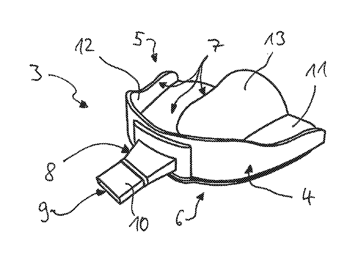
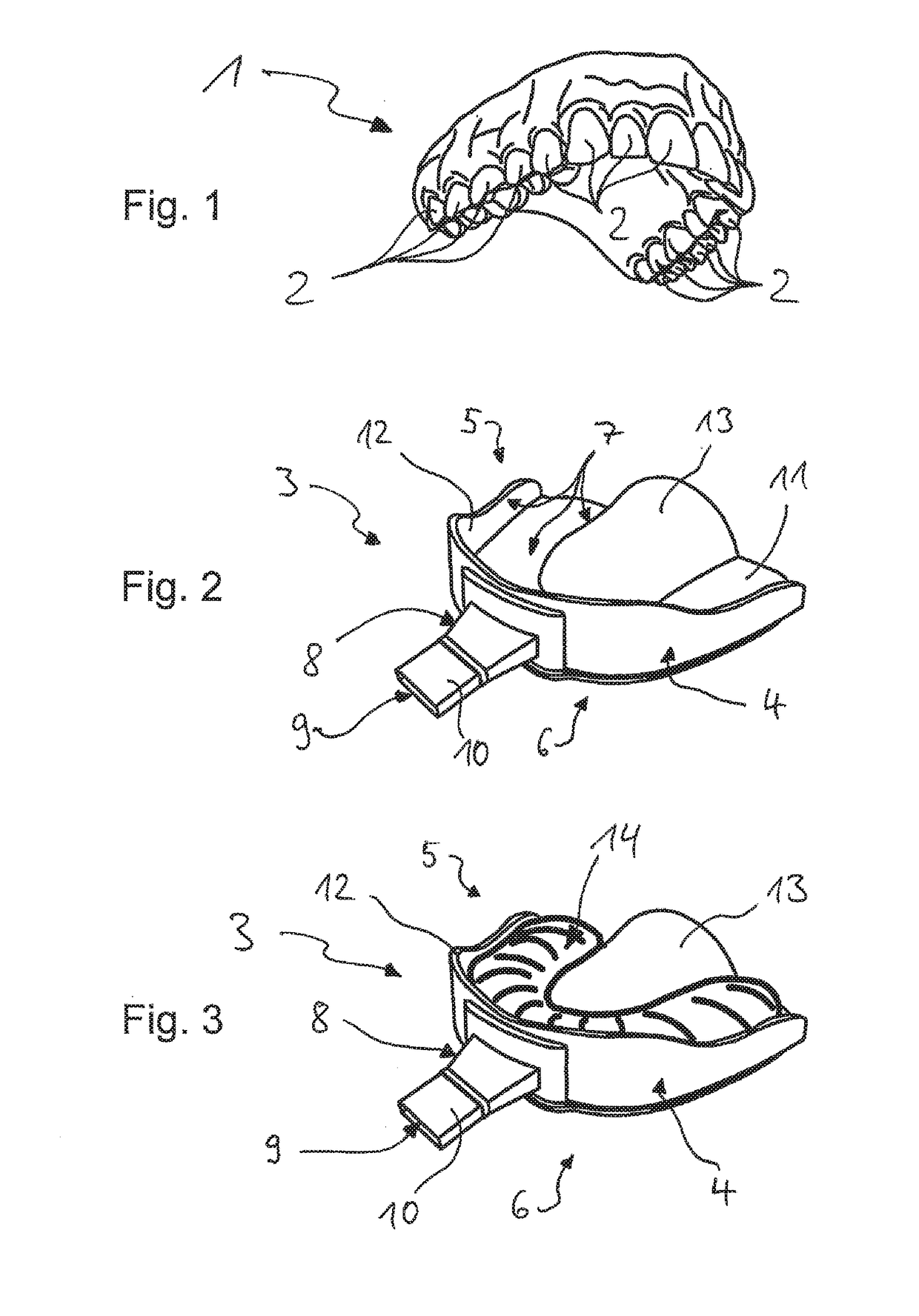
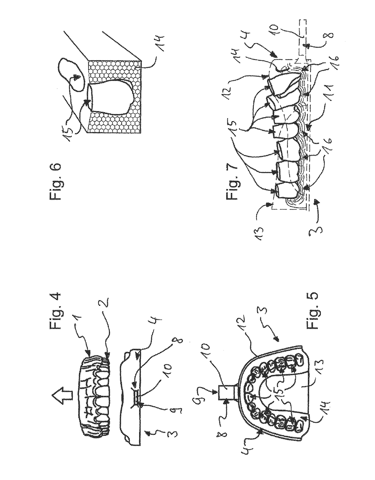
[0132]On the basis of the exemplary embodiments and examples of use that are described below and represented in the drawing, the invention is explained in more detail merely by way of example, i.e., it is not restricted to these exemplary embodiments and examples of use or to the respective combinations of features within individual exemplary embodiments and examples of use. Method and device features are also respectively obtained by analogy from descriptions of the device and method.

[0133]Individual features that are specified and / or represented in connection with actual exemplary embodiments are not restricted to these exemplary embodiments or the way in which they are combined with the other features of these exemplary embodiments, but may, to the extent that is technically feasible, be combined with any other variants, even if they are not treated separately in the present documents, and in particular with features and configurations of other exemplary embodiments.

[0134]The sam...


PUM


Abstract

The invention relates to an impression tray, which carries a deformable impression mass in order to prepare an impression of arrangements, shapes or dimensions, in or on the human body, in the mouth, and an impression of at least part of a tooth or of dental structures, wherein sensor devices are present, with which a change of at least one physical property or variable of the impression mass can be captured in a spatially resolved manner. The invention further relates to a method for capturing structures, arrangements or shapes, whereby a deformable impression compound is brought onto or into the structures, arrangements or, is introduced, into the mouth or body and a change of at least one physical property or variable of the impression compound is transmitted to sensor devices when preparing an impression and provided in a form that is suitable for electronic data processing.

Description

CROSS REFERENCES TO RELATED APPLICATIONS[0001]This application is a continuation of U.S. patent application Ser. No. 14 / 081,708, filed Nov. 15, 2013, now pending, which is a continuation of U.S. patent application Ser. No. 13 / 184,441 filed Jul. 15, 2011, which is a continuation of pending international patent application PCT / EP2009 / 006474, filed on Sep. 7, 2009 designating the U.S., which international patent application has been published in German language and claims priority from German utility model DE 20 2009 000 458.9, filed on Jan. 15, 2009, International patent application PCT / IB2009 / 006054 filed Apr. 23, 2009 and European patent application EP 09 166 523, filed Jul. 28, 2009. The entire contents of these prior applications are incorporated herein by this reference.BACKGROUND OF THE INVENTION[0002]The invention relates to impression trays, such as in particular dental impression trays, and methods for capturing structures, arrangements or shapes, such as preferably for captu...

Claims


Application Information

Patent Timeline
Patent Type & Authority Applications(United States)
IPC IPC(8): A61C9/00A61C19/04A61K6/10A61B6/14A61B6/51A61K6/90
CPCA61C9/008A61C9/0006A61K6/10A61C19/04A61B6/145A61K6/90A61B6/512A61B5/0022A61B5/0077A61C9/0053
Inventor SCHMITT, FRITZ
Owner MEDENTIC
Learn More