Electro-optic gas barrier

Active Publication Date: 2017-05-18
GENTEX CORP
View PDF6 Cites 24 Cited by
  • Summary
  • Abstract
  • Description
  • Claims
  • Application Information

AI Technical Summary

Benefits of technology

This patent describes an electro-optic element that includes a first transparent substrate with a conductive layer and a second transparent substrate with a conductive layer. A cavity is created between the two substrates and an electro-optic medium is placed inside. A barrier is used to prevent the transmission of gas between the first substrate and the electro-optic medium. The electro-optic medium is a polymer that can change from clear to darkened states. The technical effect of this patent is to provide a reliable and durable electro-optic element with a high-quality electro-optic medium and a barrier to prevent gas transmission, which can be used in various applications such as displays and optical devices.

Problems solved by technology

Environmental conditions may present constraint issues related to gas and moisture on the components of the rearview mirror assembly.

Method used


Image

  • Electro-optic gas barrier
  • Electro-optic gas barrier
  • Electro-optic gas barrier

Examples


Embodiment Construction

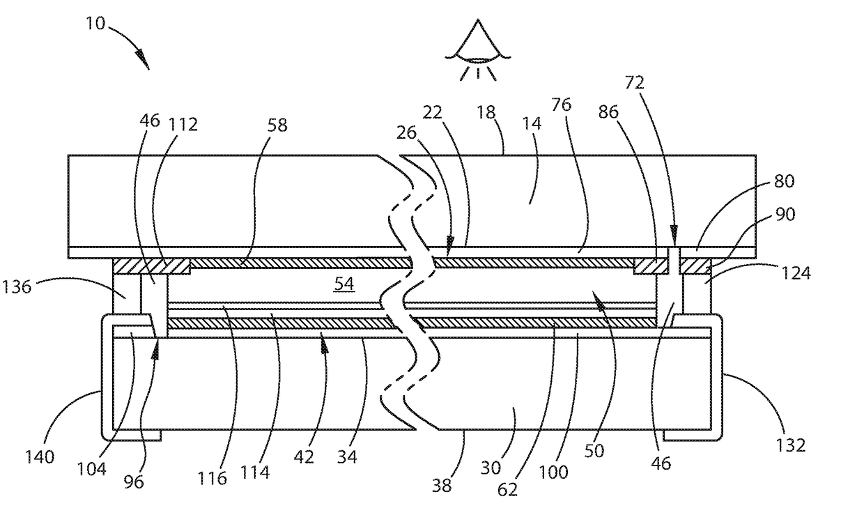
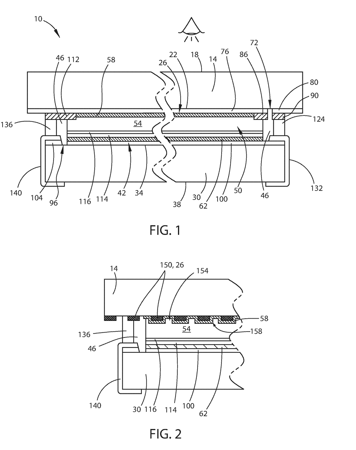
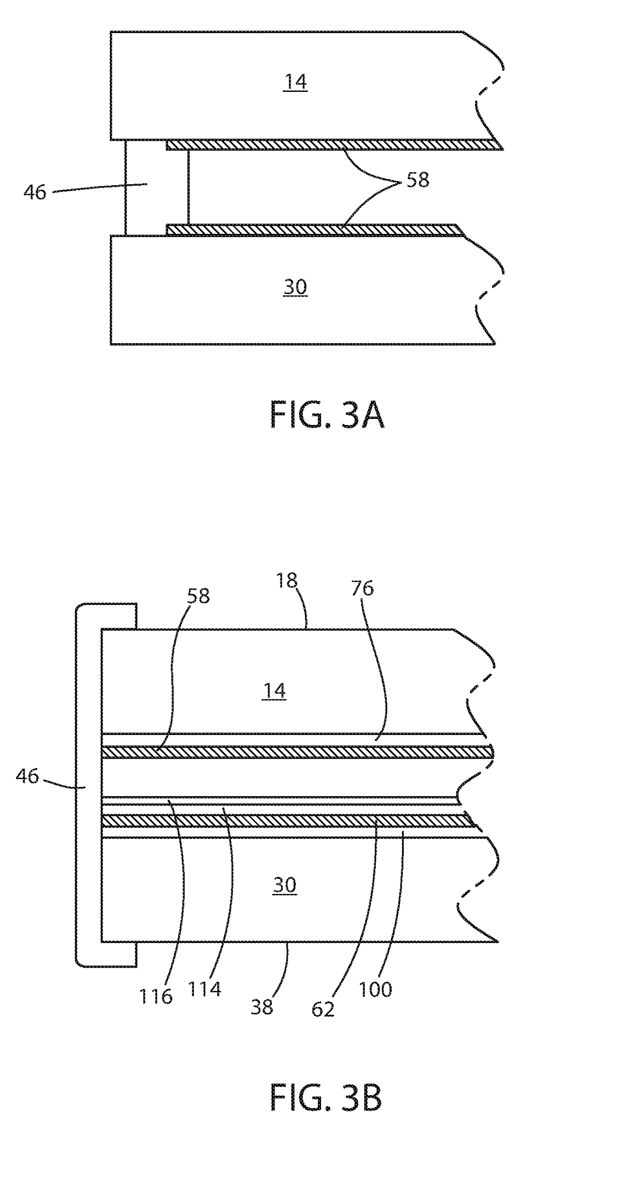
[0012]For purposes of description herein, the terms “upper,”“lower,”“right,”“left,”“rear,”“front,”“vertical,”“horizontal,” and derivatives thereof shall relate to the disclosure as oriented in FIG. 1. However, it is to be understood that the disclosure may assume various alternative orientations, except where expressly specified to the contrary. It is also to be understood that the specific devices and processes illustrated in the attached drawings, and described in the following specification, are simply exemplary embodiments of the inventive concepts defined in the appended claims. Hence, specific dimensions and other physical characteristics relating to the embodiments disclosed herein are not to be considered as limiting unless the claims expressly state otherwise.

[0013]Referring to FIGS. 1-3B, reference numeral 10 generally designates an electro-optic element having a first substantially transparent substrate 14 having a first surface 18 and second surface 22 disposed on opposi...


PUM


Abstract

An electro-optic element is provided that includes a first substantially transparent substrate having first and second surfaces disposed on opposite sides thereof. The second surface has a first electrically conductive layer and a second substantially transparent substrate has third and fourth surfaces disposed on opposite sides thereof. The third surface includes a second electrically conductive layer. At least one of the first and second substantially transparent substrates includes a polymer. A primary seal is positioned such that the primary seal and the first and second substrates define a cavity therebetween. An electro-optic medium is disposed in the cavity. The electro-optic medium is variably transmissive such that the electro-optic medium is operable between generally clear and darkened states. A polymeric barrier is disposed between the first electrically conductive layer and the electro-optic medium.

Description

CROSS-REFERENCE TO RELATED APPLICATIONS[0001]This application claims the benefit of and priority to U.S. Provisional Patent Application No. 62 / 257,136, filed on Nov. 18, 2015, entitled ELECTRO-OPTIC GAS BARRIER, the entire disclosure of which is hereby incorporated herein by reference.BACKGROUND OF THE DISCLOSURE[0002]Vehicles typically include a rearview mirror system to allow a driver of the vehicle to observe behind the vehicle. Environmental conditions may present constraint issues related to gas and moisture on the components of the rearview mirror assembly.SUMMARY OF THE DISCLOSURE[0003]According to one aspect of the present disclosure, an electro-optic element is provided that includes a first substantially transparent substrate having first and second surfaces disposed on opposite sides thereof. The second surface has a first electrically conductive layer and a second substantially transparent substrate has third and fourth surfaces disposed on opposite sides thereof. The th...

Claims


Application Information

Patent Timeline
IPC IPC(8): G02F1/153B60R1/08
CPCG02F1/1533G02F2001/1536B60R1/088
Inventor TONAR, WILLIAM L.
Owner GENTEX CORP
Why Eureka
Try Eureka