

Three-dimensional shaping apparatus and three-dimensional shaping system
a three-dimensional shaping and shaping technology, applied in the direction of additive manufacturing processes, manufacturing tools, additive manufacturing with solid and fluid, etc., can solve the problem of dispersed powder contamination on the inside of the apparatus
- Summary
- Abstract
- Description
- Claims
- Application Information
AI Technical Summary
Benefits of technology
Problems solved by technology
Method used
Image

Examples
first embodiment
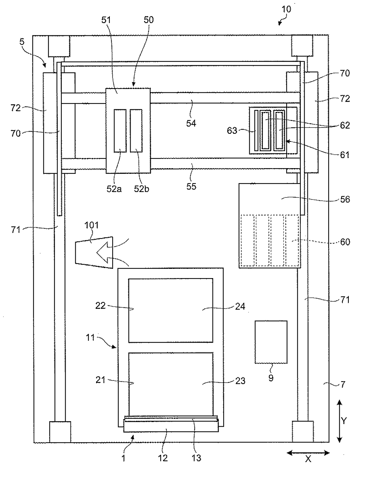
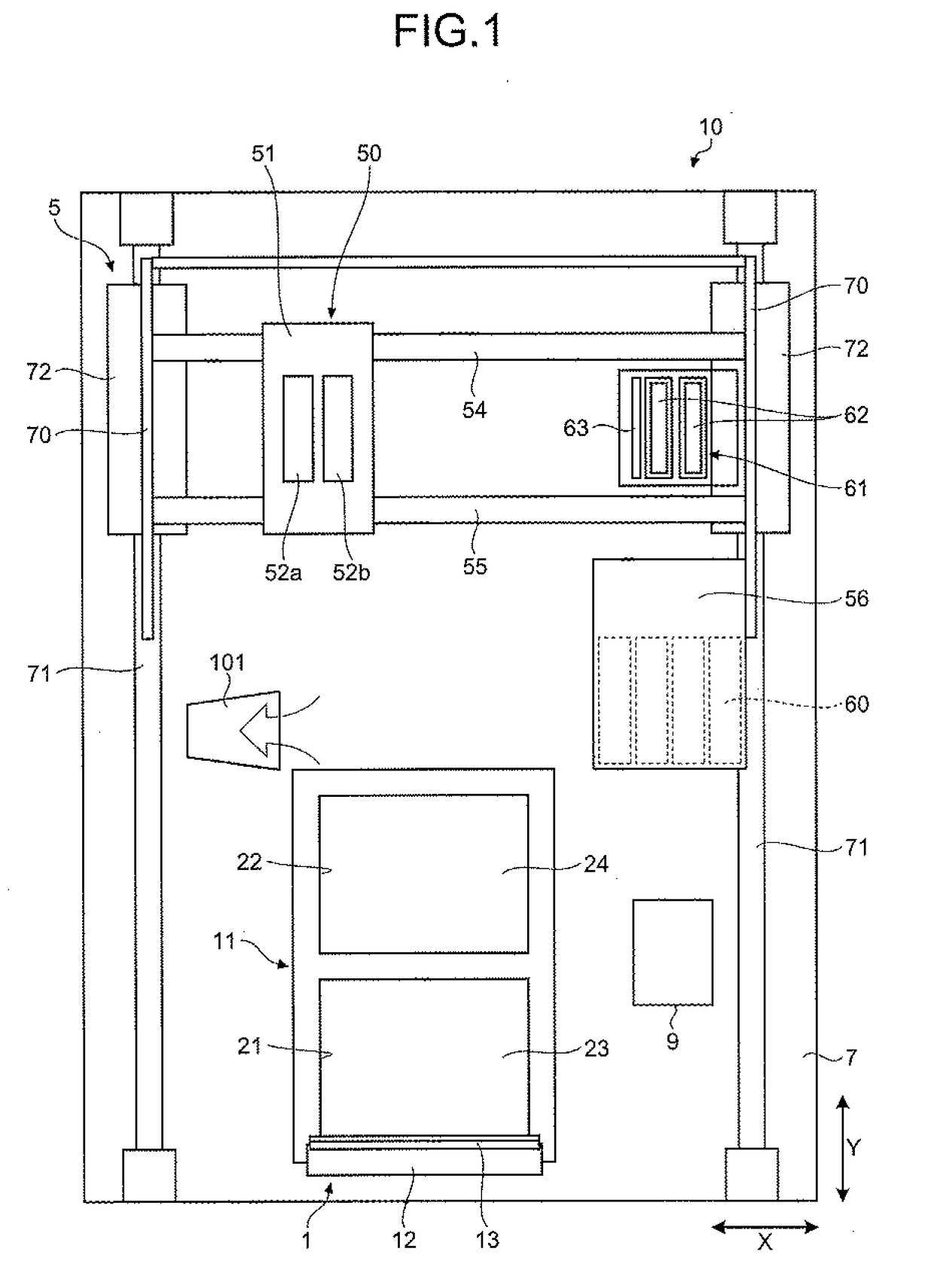
[0031]FIG. 1 is a top view schematically illustrating an example configuration of a three-dimensional shaping apparatus according to a first embodiment. FIG. 2 is a side view schematically illustrating the example configuration of the three-dimensional shaping apparatus illustrated in FIG. 1.
[0032]As illustrated in FIG. 1 and FIG. 2, a three-dimensional shaping apparatus 10 is a powder lamination shaping apparatus and includes a shaping section 1 and a shaping unit (ejector) 5. In the shaping section 1, shaped layers, each of which is a layered and shaped object formed by binding powder (powdered material) 20, are to be formed. The shaping unit 5 ejects a shaping liquid to a powder layer, which is a layer of the powder 20 that is evenly spread, in the shaping section 1 to shape a 3D shaped object.
[0033]The shaping section 1 includes a powder chamber 11 and a recoater roller 12, which is a rotary member serving as a leveling member (recoater). As the leveling member, for example, a p...
second embodiment
[0076]In the first embodiment described above, the powder chamber 11 of the shaping section 1 includes two chambers: the feeding chamber 21 and the shaping chamber 22; however, the feeding chamber 21 may be omitted. When omitted, a configuration for supplying the powder 20 from a powder supply device to the shaping chamber 22 and flattening the fed powder 20 with leveling means may preferably be employed. Such a configuration, from which the feeding chamber 21 is omitted, is described in detail below as a second embodiment with reference to the drawings.
[0077]FIG. 10 is a side view schematically illustrating an example configuration of a three-dimensional shaping apparatus according to the second embodiment. The second embodiment is similar in configuration to the above-described first embodiment except for the configuration illustrated in FIG. 10, and repeated detailed description is omitted.
[0078]As illustrated in FIG. 10, a shaping section 2 according to the second embodiment is ...
third embodiment
[0085]In each of the above-described embodiments, the configuration, in which the powder 20 that is suspended in air to form the cloud 20b in the traveling direction of the recoater roller 12 when the recoater roller 12 is stopped is collected through the suction inlet 101, is illustrated. In a third embodiment, a configuration that can collect, in addition to the powder 20 suspended in air to form the cloud 20b near the stop position of the recoater roller 12, a surplus amount of the powder 20 falling from an edge of the shaping chamber 22 when the top surface of the shaping chamber 22 is flattened with the recoater roller 12 is described through an example.
[0086]FIG. 12 is a top view schematically illustrating an example configuration of a three-dimensional shaping apparatus according to the third embodiment. FIG. 13 is a side view schematically illustrating an example configuration of the powder chamber and a collecting unit of the three-dimensional shaping apparatus illustrated ...
PUM
| Property | Measurement | Unit |
|---|---|---|
| Temperature | aaaaa | aaaaa |
| Particle size | aaaaa | aaaaa |
| Humidity | aaaaa | aaaaa |
Abstract
Description
Claims
Application Information