
Electronic device

Inactive Publication Date: 2017-06-01
ALSON TECH LTD
View PDF1 Cites 0 Cited by
  • Summary
  • Abstract
  • Description
  • Claims
  • Application Information

AI Technical Summary

Benefits of technology

The invention provides an electronic device with a display screen that can show different states based on a processing unit. This device is more eye-pleasing and convenient for users as the display screen can show different patterns to indicate the device's state.

Problems solved by technology

In addition, when the memory does not function normally, a user is unable to know the state of the memory (for example, capacity and temperature) from the appearance of the memory to find out the cause.

Method used


Image

  • Electronic device
  • Electronic device
  • Electronic device

Examples


Embodiment Construction

[0015]The present invention will be clearer from the following description when viewed together with the accompanying drawings, which show, for purpose of illustrations only, the preferred embodiment in accordance with the present invention.

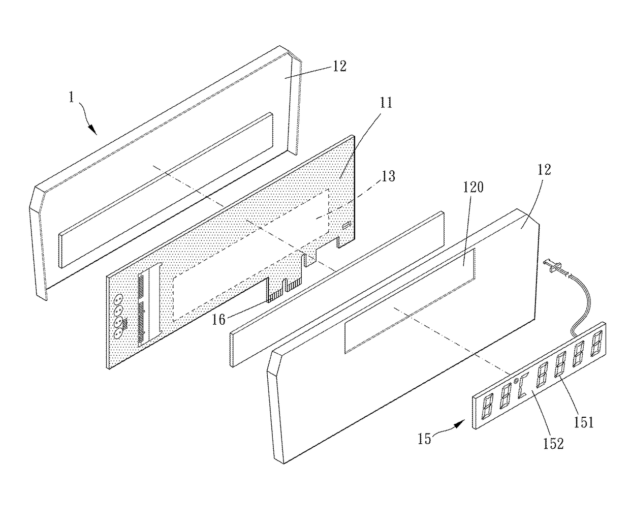
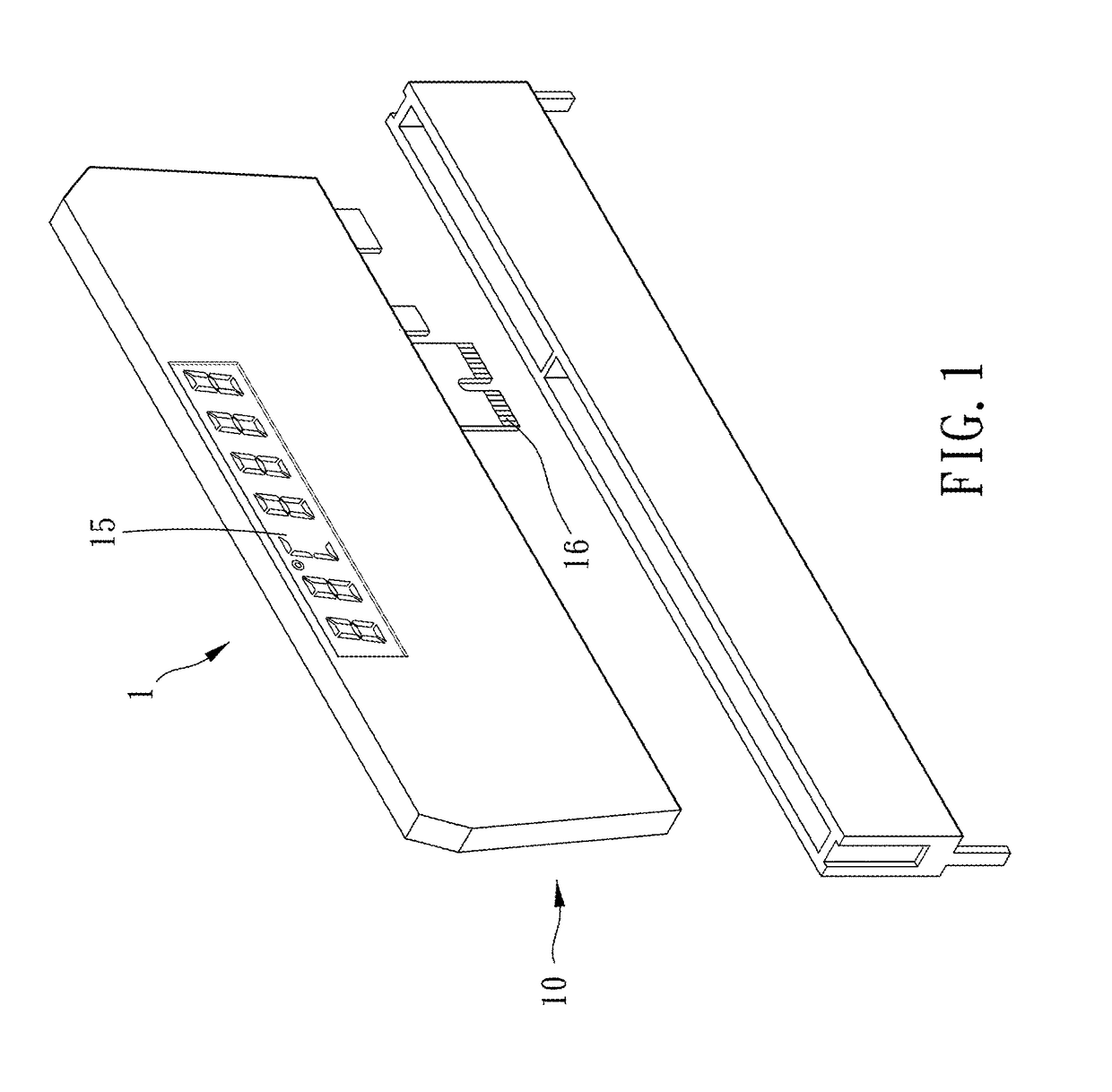
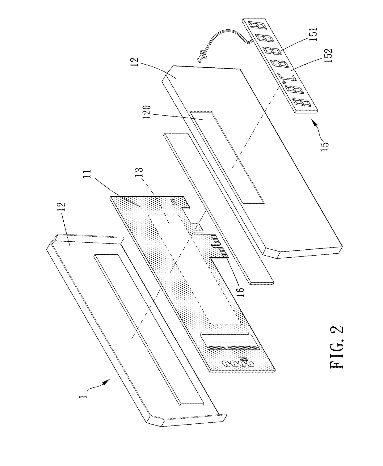
[0016]Please refer to FIGS. 1 to 3 for a preferred embodiment of the present invention. An electronic device 1 includes a main body 10, a processing unit 14, a display screen 15 and a PCI-E insert row 16.

[0017]The main body 10 has a substrate 11 and a shell portion 12 disposed by two opposite side faces of the substrate 11, the substrate 11 is provided with an electronic unit 13, and the processing unit 14 is disposed in the main body 10.

[0018]In this embodiment, the PCI-E insert row 16 is disposed on the substrate 11, and the PCI-E insert row 16 is electrically connected with the electronic unit 13. More specifically, to meet different requirements, the electronic unit 13 may be a graphic processing unit or a display processing unit, and the ele...


PUM


Abstract

An electronic device, including a main body, a processing unit, a display screen and a PCI-E insert row. The main body has a substrate and a shell portion disposed by two opposite side faces of the substrate, the substrate is provided with an electronic unit; the processing unit is disposed in the main body; the display screen is attached to the main body and viewable from outside of the electronic device, the display screen is electrically connected with the processing unit, the processing unit can control a display state of the display screen; and the PCI-E insert row is disposed on the substrate, and the PCI-E insert row is electrically connected with the electronic unit.

Description

BACKGROUND OF THE INVENTION[0001]Field of the Invention[0002]The present invention relates to an electronic device.[0003]Description of the Prior Art[0004]An electronic device as disclosed in TW201520737 includes a substrate, a boosting circuit and a plasma tube. The boosting circuit is disposed on the substrate and electrically connected with two power output ends; and two opposite ends of the plasma tube have two electrodes electrically connected the two power output ends.[0005]When in actual practice, the plasma tube of the conventional electronic device has limited variations.[0006]In addition, when the memory does not function normally, a user is unable to know the state of the memory (for example, capacity and temperature) from the appearance of the memory to find out the cause.[0007]The present invention has arisen to mitigate and / or obviate the afore-described disadvantages.SUMMARY OF THE INVENTION[0008]The major object of the present invention is to provide an electronic de...

Claims


Application Information

Patent Timeline
IPC IPC(8): G06T1/20G09G3/14
CPCG09G3/14G06T1/20
Inventor CHENG, HAN-HUNGKUO, CHI-FEN
Owner ALSON TECH LTD
Learn More