
Solid state disk

a solid state disk and disk drive technology, applied in the direction of error detection/correction, input/output to record carriers, instruments, etc., can solve the problems of user's inability to know the state of the memory, not easy to assemble or replace, and the screen of the wall module is not disclosed, so as to achieve the effect of being more pleasant to the ey

Inactive Publication Date: 2017-10-26
ALSON TECH LTD
View PDF13 Cites 0 Cited by
  • Summary
  • Abstract
  • Description
  • Claims
  • Application Information

AI Technical Summary

Benefits of technology

The present invention is a solid state disk that can display various states based on a processing unit. Compared to conventional light-emitting diodes, the solid state disk is more pleasant to the eye and allows users to easily understand its state through the pattern variations on the display screen. Overall, this invention provides a more convenient and user-friendly experience for users.

Problems solved by technology

In addition, when the memory does not function normally, a user is unable to know the state of the memory (for example, capacity and temperature) from the appearance of the memory to find out the cause.
Additionally, the display screen of the wall module does not disclose that the display screen shows the conditions of the building or air qualities in different colors at the same time.
US20130145054 discloses that the display is fixed to the case of the data storage system and not detachable, so that it is not easy to assemble or replace.

Method used


Image

  • Solid state disk
  • Solid state disk
  • Solid state disk

Examples


Embodiment Construction

[0016]The present invention will be clearer from the following description when viewed together with the accompanying drawings, which show, for purpose of illustrations only, the preferred embodiment in accordance with the present invention.

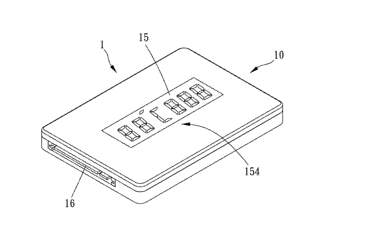
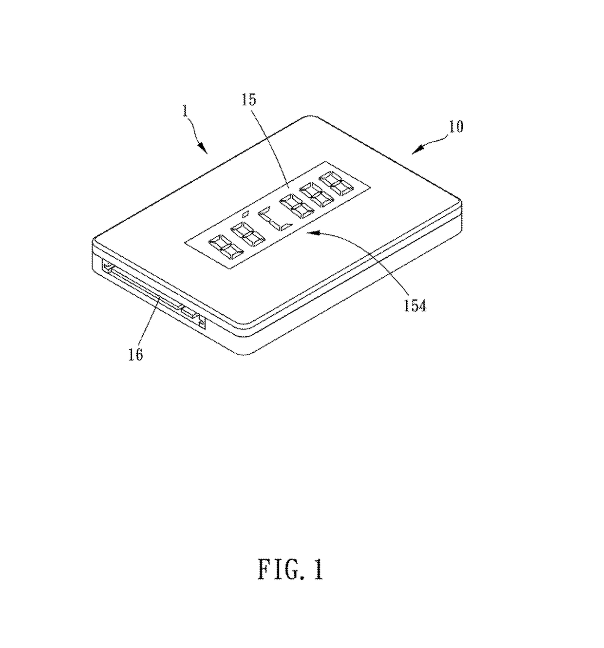
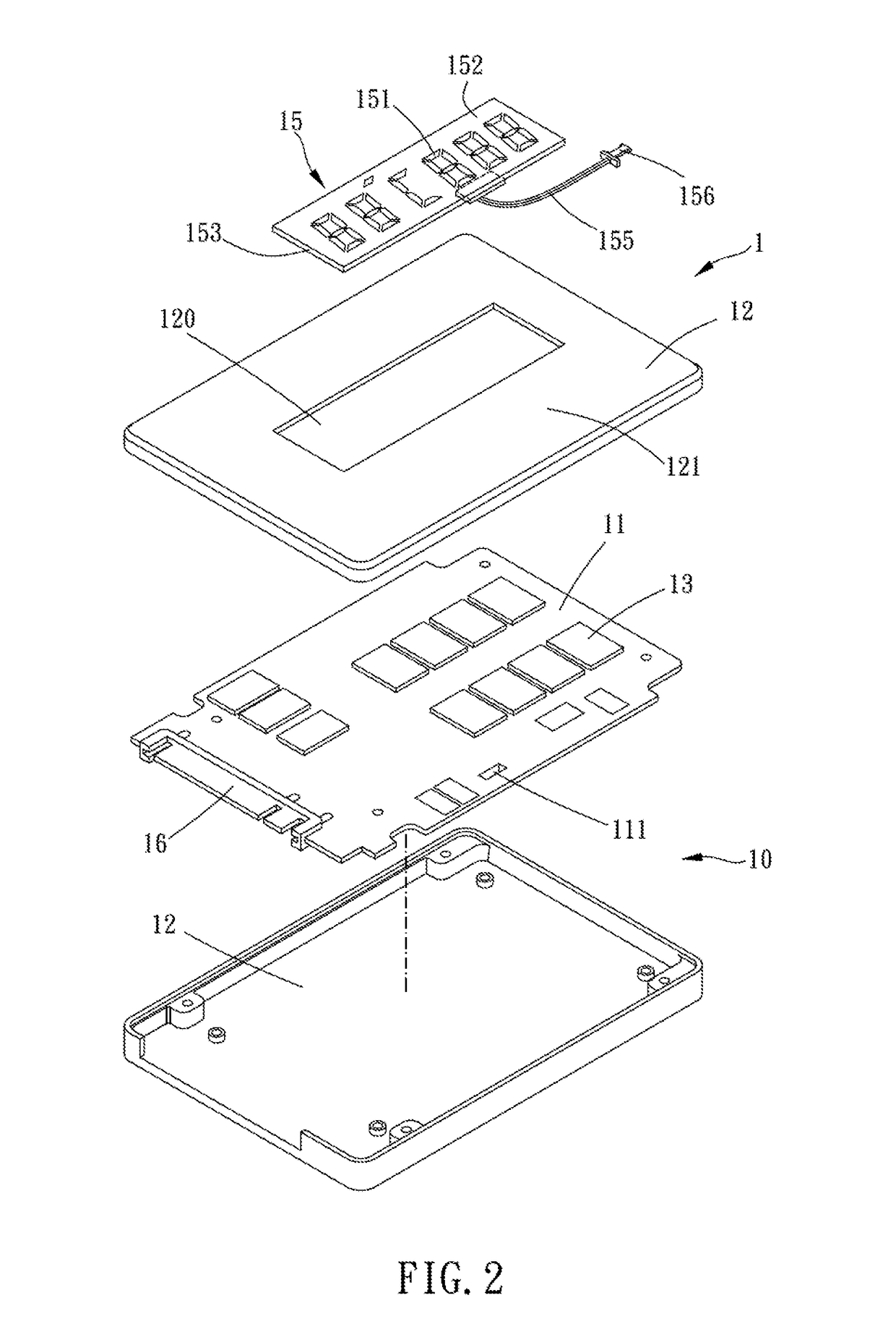
[0017]Please refer to FIGS. 1 to 3 for a preferred embodiment of the present invention. A solid state disk 1 includes a main body 10, a processing unit 14, a display screen 15 and a transmit port 16.

[0018]The main body 10 has a substrate 11 and a shell portion 12 covering two opposite side faces of the substrate 11, the substrate 11 is provided with a memory module 13, and the processing unit 14 is disposed in the main body 10.

[0019]In this embodiment, the transmit port 16 is disposed on the substrate 11, and the transmit port 16 is electrically connected with the memory module 13. More specifically, to cooperate with different insert slots in different specifications, the transmit port 16 may be a USB, a SATA or an IDE transmit port.

[0020]The di...


PUM


Abstract

A solid state disk, including a main body, a processing unit, a display screen and a transmit port. The main body has a substrate and a shell portion covering on two opposite side faces of the substrate, the substrate is provided with a memory module; the processing unit is disposed in the main body; the display screen is attached to the main body and viewable from outside of the solid state disk, the display screen is electrically connected with the processing unit, the processing unit can control a display state of the display screen; and the transmit port is disposed on the substrate, and the transmit port is electrically connected with the memory module.

Description

[0001]The present invention is a CIP of application Ser. No. 14 / 955,953, filed Dec. 1, 2015, the entire contents of which are hereby incorporated by reference.BACKGROUND OF THE INVENTIONField of the InventionDescription of the Prior Art[0002]A solid state disk as disclosed in TWM508102 includes a substrate, a flash memory module, at least one light-emitting diode and at least one light-guiding portion. The substrate has a transmit port; the flash memory module is assembled to the substrate, and the flash memory module and the transmit port are electrically connected with each other; the at least one light-emitting diode is disposed on the substrate, and the at least one light-emitting diode and the transmit port are electrically connected with each other; and the at least one light-guiding portion at least partially covers the at least one light-emitting diode.[0003]When in actual practice, the light-emitting diode of the conventional solid state disk has limited variations.[0004]In...

Claims


Application Information

Patent Timeline
Patent Type & Authority Applications(United States)
IPC IPC(8): G06F3/06
CPCG06F3/0653G06F3/0679G06F3/0604G06F11/3037G06F11/3058G06F11/325G11C5/04
Inventor CHENG, HAN-HUNGKUO, CHI-FEN
Owner ALSON TECH LTD
Learn More