RF Filter

a filter and filter technology, applied in the field of rf filters, can solve the problems of complex and expensive production, large front-end modules in which the filters are arranged, and tuning itself altering the important properties of filters

Inactive Publication Date: 2017-06-01
SNAPTRACK
View PDF6 Cites 1 Cited by
  • Summary
  • Abstract
  • Description
  • Claims
  • Application Information

AI Technical Summary

Benefits of technology

[0007]Embodiments of the invention provide RF filters which enable tuning without altering other important paramete...

Problems solved by technology

Although modern RF filters in the meantime can be produced with small dimensions, on account of their multiplicity and the complexity of their interconnection the front-end modules in which the filters are arranged are nev...

Method used


Image

  • RF Filter
  • RF Filter
  • RF Filter

Examples


Embodiment Construction

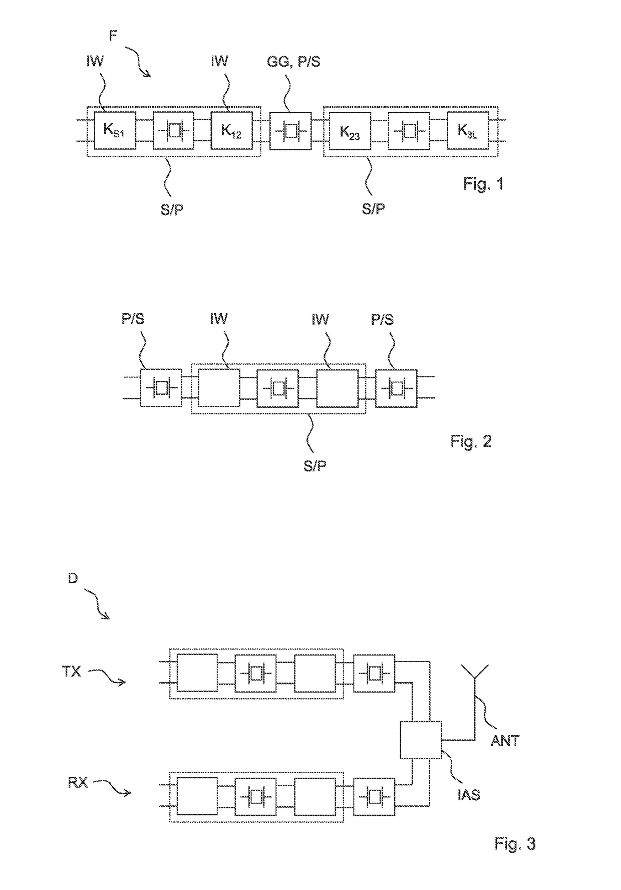
[0080]FIG. 1 shows an RF filter circuit F having three resonators and four impedance converters IW. The central resonator here represents a basic element GG. The central resonator can be a parallel resonator P or a series resonator S. The two impedance converters IW surrounding the first resonator have the effect that the resonator looks like a series resonator or like a parallel resonator toward the outside. If the central resonator is a parallel resonator, then the first resonator can also be a parallel resonator that looks like a series resonator toward the outside. Correspondingly, the third resonator would then also be a parallel resonator that looks like a series resonator toward the outside. Conversely, the central resonator can be a series resonator S. The two outer resonators would then also be series resonators that look like parallel resonators toward the outside. In this regard, using the impedance converters IW a filter structure similar to a ladder-type can be obtained...


PUM


Abstract

An RF filter is disclosed. In an embodiment, the RF filter includes series-interconnected basic elements, each basic element having an electroacoustic resonator and impedance converters interconnected in series between the basic elements, wherein the impedance converters are admittance inverters, wherein the resonators of the basic elements are parallel resonators only, and wherein at least one of the resonators is tunable.

Description

[0001]This patent application is a national phase filing under section 371 of PCT / EP2015 / 065377, filed Jul. 6, 2015, which claims the priority of German patent application 10 2014 111 904.5, filed Aug. 20, 2014, each of which is incorporated herein by reference in its entirety.TECHNICAL FIELD[0002]The invention relates to RF filters which can be used, e.g., in portable communication devices.BACKGROUND[0003]Portable communication devices, e.g., mobile radio devices, in the meantime can enable communication in a multiplicity of different frequency bands and for a multiplicity of different transmission systems. To that end, they generally comprise a multiplicity of RF filters each provided for the corresponding frequency and the corresponding transmission system. Although modern RF filters in the meantime can be produced with small dimensions, on account of their multiplicity and the complexity of their interconnection the front-end modules in which the filters are arranged are neverth...

Claims


Application Information

Patent Timeline
IPC IPC(8): H03H9/54H01P5/16H04L5/14H03H7/18
CPCH03H9/545H04L5/1461H01P5/16H03H7/18H03H9/542H03H9/6403H03H9/6483
Inventor SCHMIDHAMMER, EDGAR
Owner SNAPTRACK
Why Eureka
Try Eureka