
Precision microwave frequency synthesizer and receiver with delay balanced drift canceling loop

a frequency synthesizer and frequency receiver technology, applied in the field of frequency synthesizers and receivers, can solve the problems that known synthesizers typically have not adequately addressed situations, and the unsuitability of many applications of synthesizers, and achieve low phase noise, fine tunable, and significant signal modulation capability.

Active Publication Date: 2020-11-24
GIGA TRONICS
View PDF3 Cites 3 Cited by
  • Summary
  • Abstract
  • Description
  • Claims
  • Application Information

AI Technical Summary

Benefits of technology

The solution provides low phase noise, fine tunability, and rapid frequency switching within 500 nanoseconds, enhancing signal modulation capabilities and phase stability, facilitating effective radar testing and direction finding system calibration.

Problems solved by technology

Frequency synthesizers using noise or drift canceling loops are well known for providing low phase noise and short phase & frequency settling times. However, known synthesizers have been found unsuitable for many applications, such as threat simulation and radar target generation, due to their failure to provide satisfactory signal modulation within the generator and their lack of phase coherent frequency switching characteristics.
Known synthesizers typically have not adequately addressed situations that require the coordination of multiple channels.

Method used


Image

  • Precision microwave frequency synthesizer and receiver with delay balanced drift canceling loop
  • Precision microwave frequency synthesizer and receiver with delay balanced drift canceling loop
  • Precision microwave frequency synthesizer and receiver with delay balanced drift canceling loop

Examples


Embodiment Construction

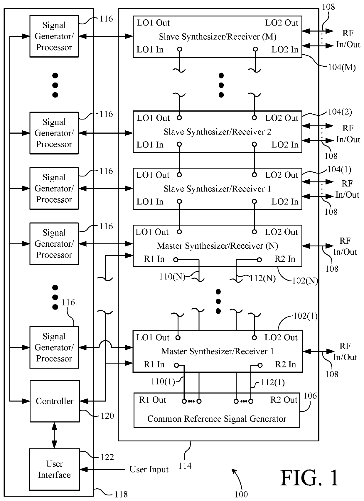
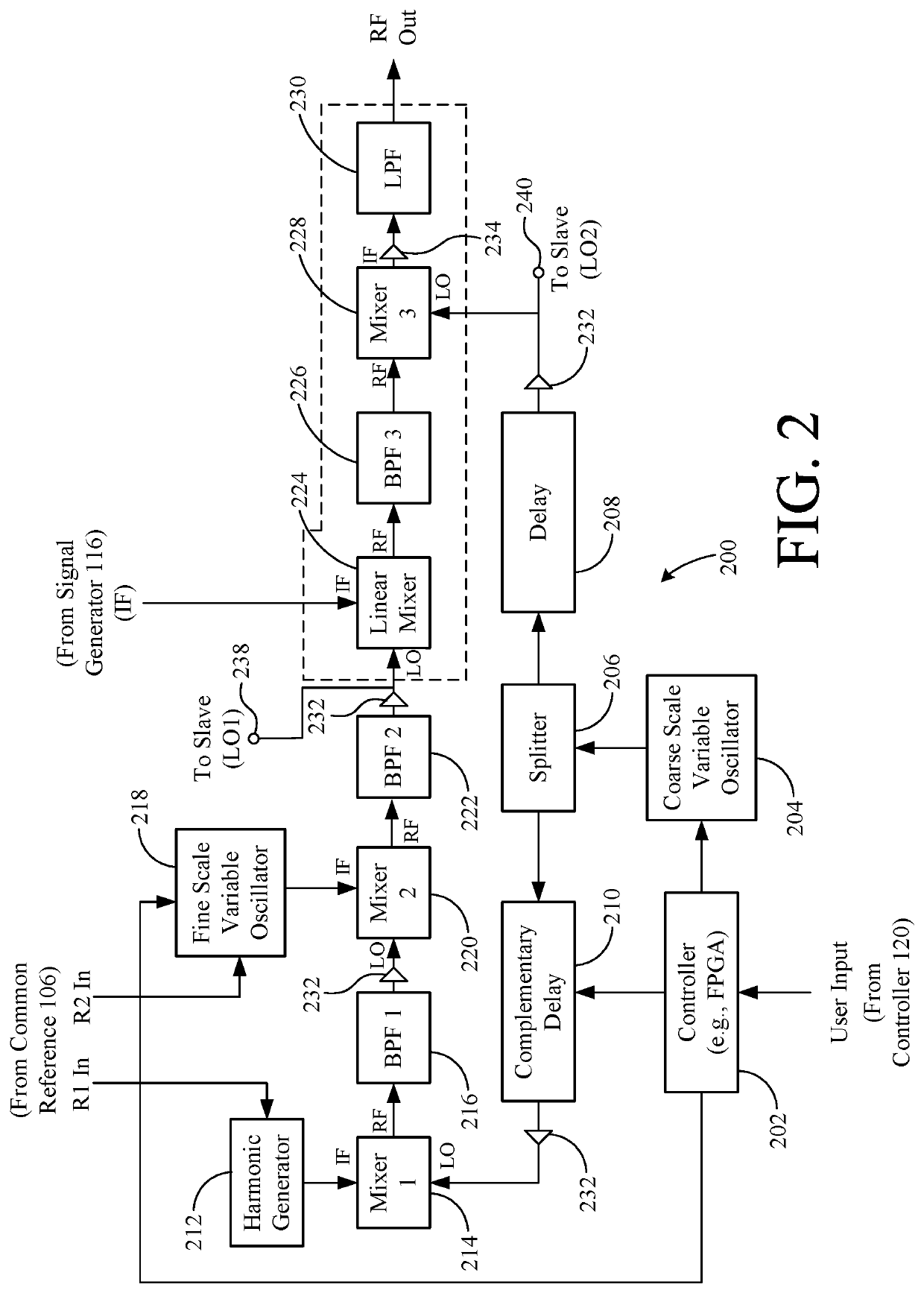
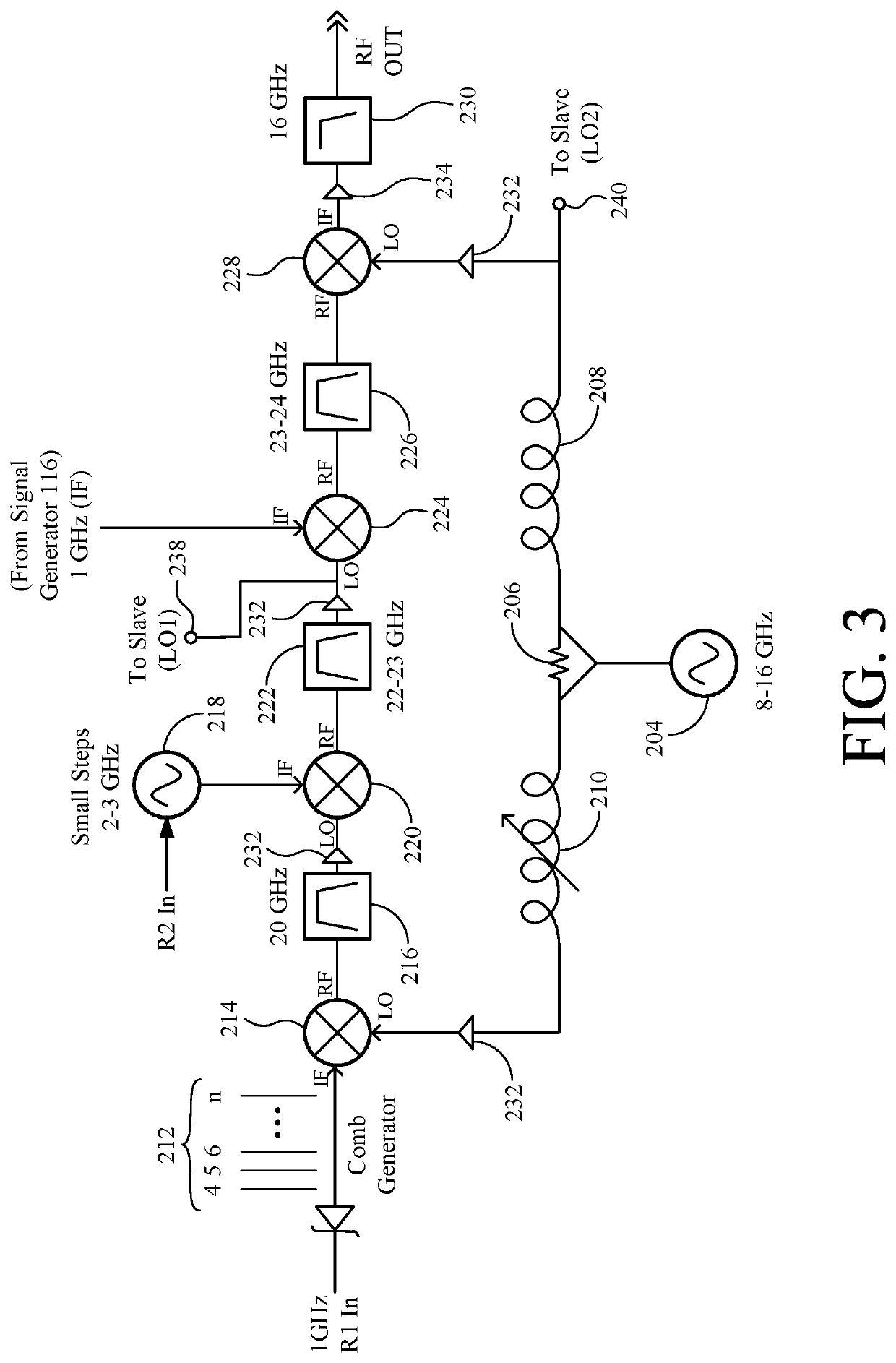
[0031]The present invention overcomes the problems associated with the prior art, by providing a frequency converter (synthesizer or receiver) that includes a drift canceling loop with a balanced delay and a linear signal path (e.g., in the up-converter). In the following description, numerous specific details are set forth (e.g., oscillator frequencies, filter frequencies, delay values, etc.) in order to provide a thorough understanding of the invention. Those skilled in the art will recognize, however, that the invention may be practiced apart from these specific details. In other instances, details of well-known microwave synthesizer components, design, and use have been omitted, so as not to unnecessarily obscure the present invention.

[0032]Several aspects of the present invention will be apparent to those skilled in the art based on the content of the drawings, which alone will enable a person of ordinary skill in the art to make and use the disclosed inventions without undue e...


PUM


Abstract

An example frequency converter includes a drift canceling loop with a balanced delay and a linear signal path (e.g., linear with respect to frequency scaling, amplitude modulation, and / or phase modulation). One side of the drift canceling loop includes a fixed delay, and the opposite side includes an adjustable, complementary delay. The adjustable, complementary delay facilitates precision matching of the signal delays on each side of the loop over a range of frequencies, which results in a significant improvement in noise cancellation, particularly at large offsets to the carrier, while permitting the use of a higher noise, but very fast tuning course scale oscillator. The linear signal path from the signal generator to an RF output facilitates modulation of the signal by the signal generator. A modular format is an advantageous embodiment of the invention that includes the removal of the frequency synthesizer's low phase noise reference into a separate module.

Description

RELATED APPLICATIONS[0001]This application is a continuation of U.S. patent application Ser. No. 15 / 636,515, filed on Jun. 28, 2017 by at least one common inventor, which claims the right of priority to co-pending U.S. Provisional Patent Application No. 62 / 355,553, filed on Jun. 28, 2016 by at least one common inventor, both of which are incorporated herein by reference in their entireties.BACKGROUND OF THE INVENTIONField of the Invention[0002]This invention relates generally to frequency synthesizers and receivers, and more particularly to frequency synthesizers and receivers in the microwave region.Description of the Background Art[0003]Frequency synthesizers using noise or drift canceling loops are well known for providing low phase noise and short phase & frequency settling times. However, known synthesizers have been found unsuitable for many applications, such as threat simulation and radar target generation, due to their failure to provide satisfactory signal modulation withi...

Claims


Application Information

Patent Timeline
Patent Type & Authority Patents(United States)
IPC IPC(8): H03K5/159H04B1/16H03L7/16H03K5/00H03B21/01
CPCH04B1/16H03B21/01H03L7/16H03K5/159H03K2005/00058H03D7/161H04B1/0475H04B1/525H04J2203/0069H04B7/2121H04Q2213/394H04W76/00
Inventor REGAZZI, JOHN R.LEWIS, CHARLESFUENTES, CARLOS
Owner GIGA TRONICS
Learn More