60 GHz Frequency Generator Incorporating Third Harmonic Boost And Extraction

a frequency generator and third harmonic technology, applied in the field of oscillation generators, can solve the problems of poor pn, limited tr, high power consumption of cmos implementations of such 60 ghz los, etc., and achieve the effect of improving system level efficiency and phase nois

Active Publication Date: 2016-04-07
SHORT CIRCUIT TECH LLC
View PDF0 Cites 38 Cited by
  • Summary
  • Abstract
  • Description
  • Claims
  • Application Information

AI Technical Summary

Benefits of technology

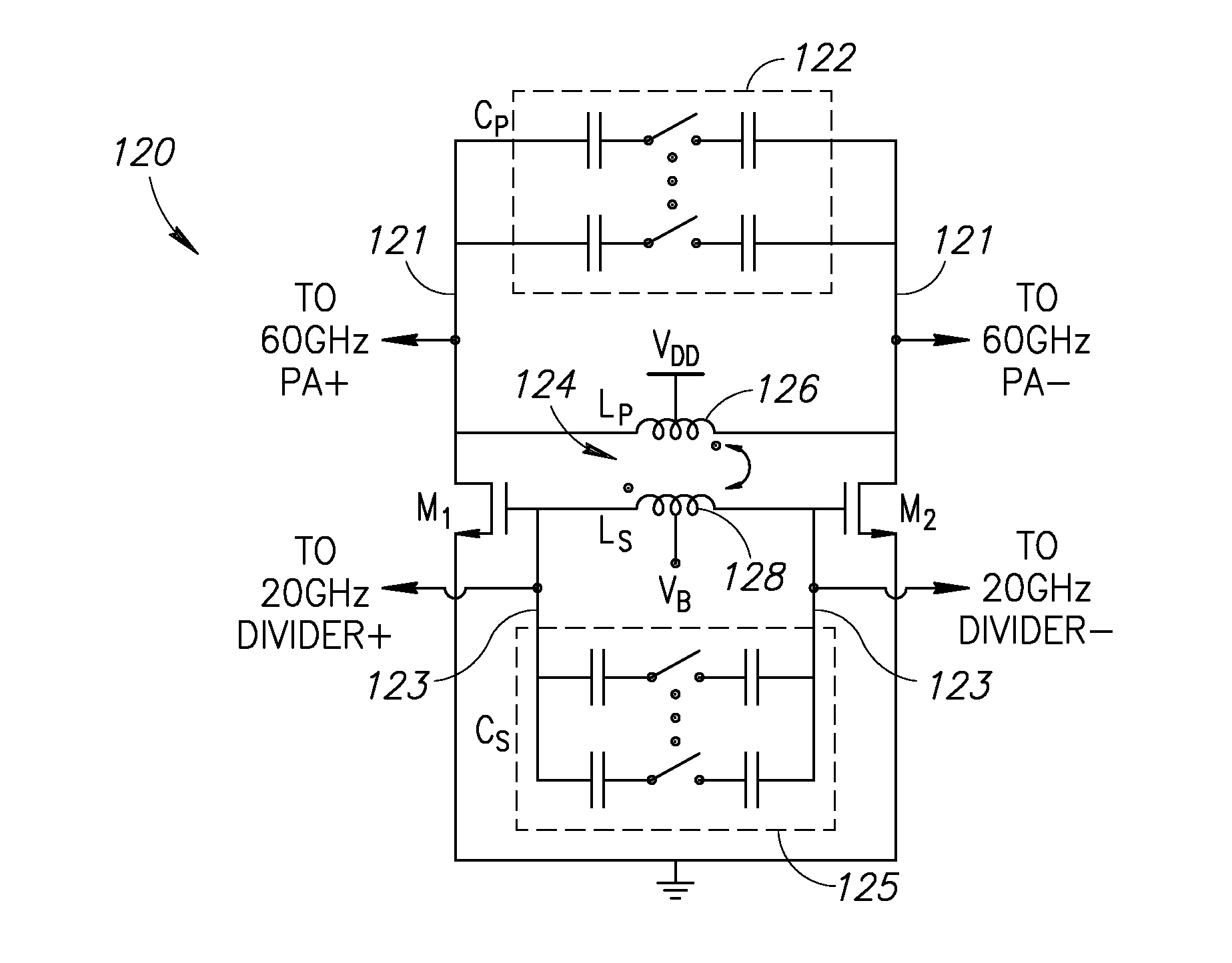
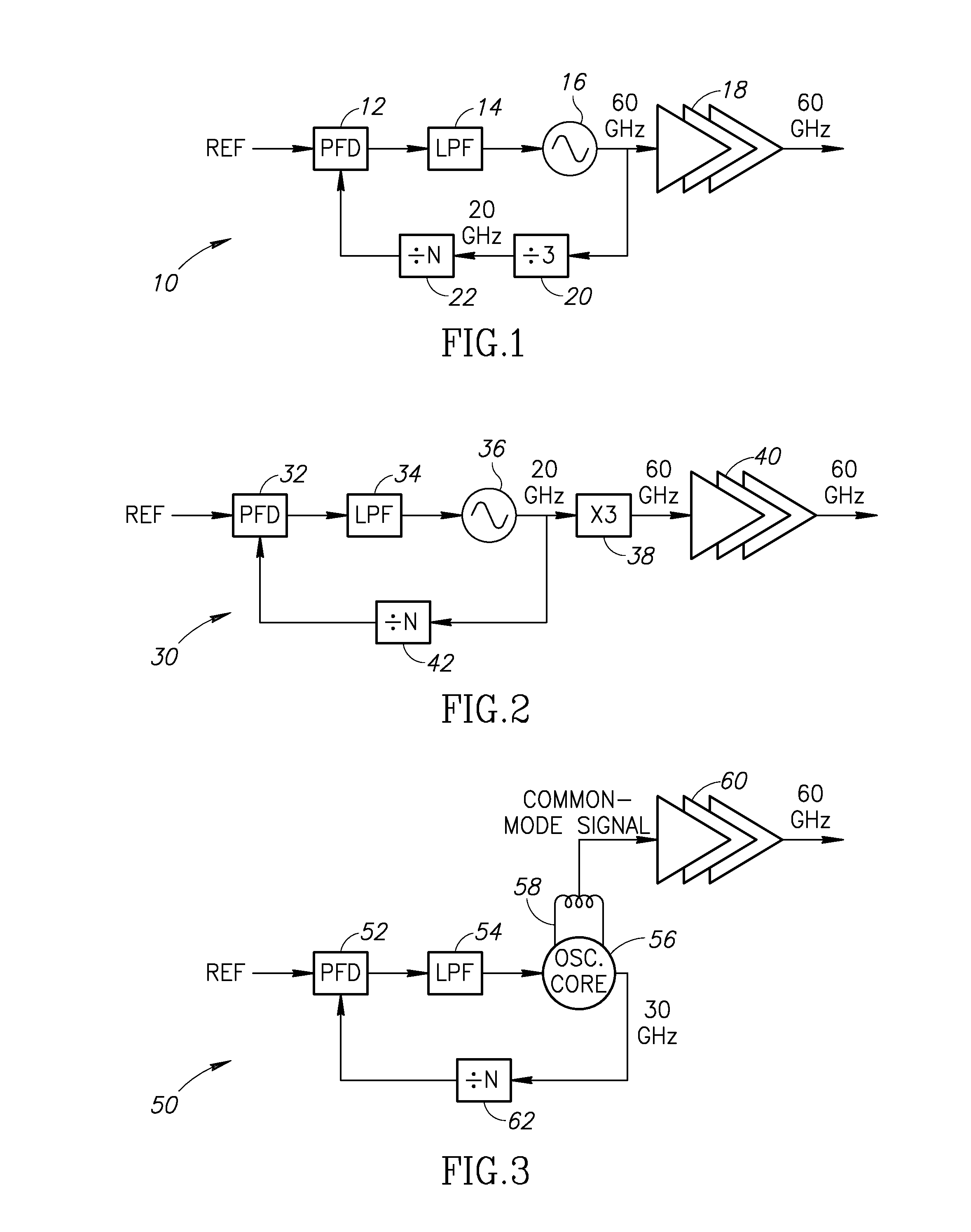
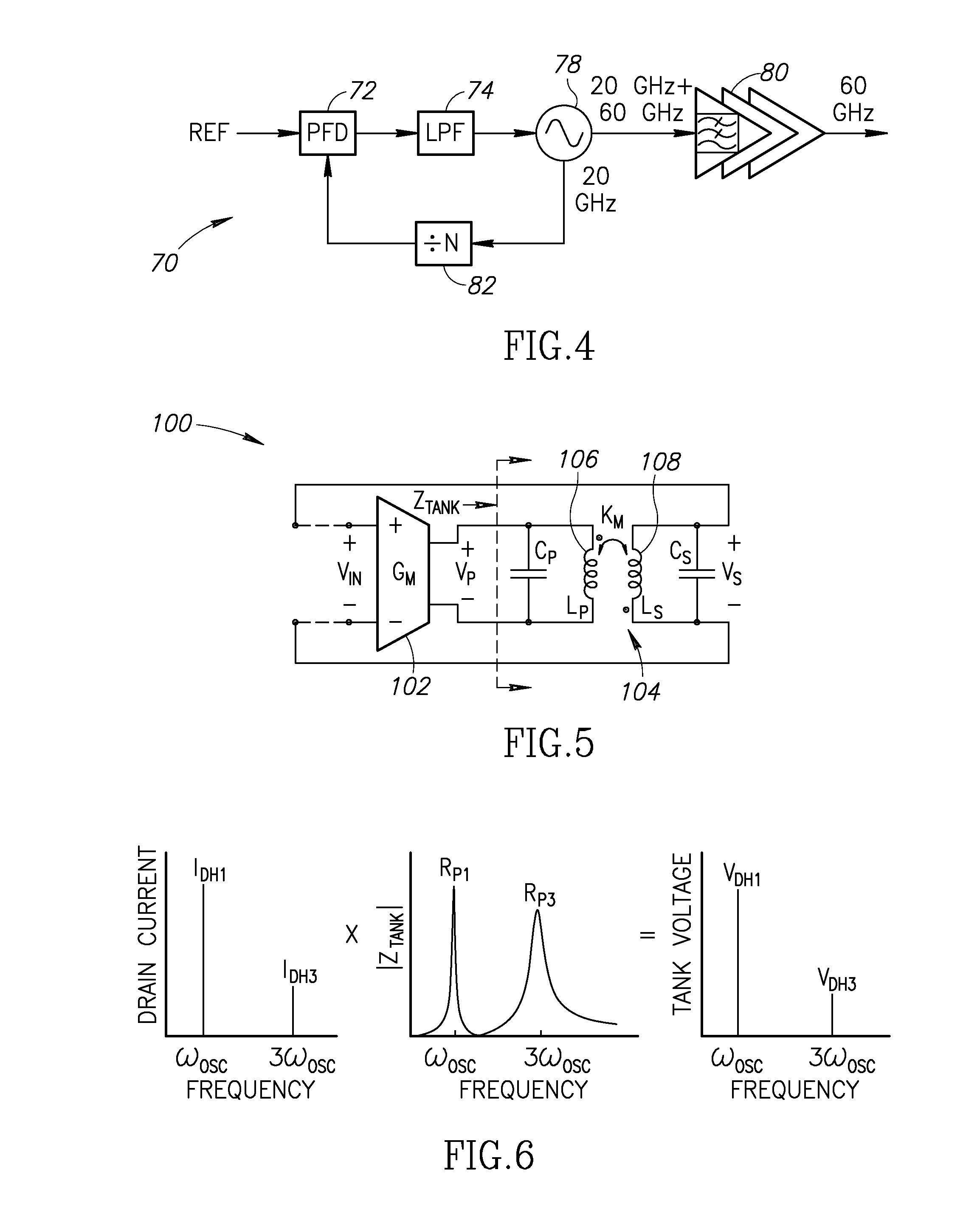
[0005]The present invention is a frequency generator incorporating an implicit divide by three divider (i.e. third harmonic extraction) suitable for use at 60 GHz providing improved system level efficiency and phase noise. The frequency generator employs a third harmonic boosting technique to increase the third harmonic at the output of the oscillator. The oscillator generates both ˜20 GHz fundamental and a significant amount of the third harmonic at ˜60 GHz thus avoiding the need for a frequency divider operating at 60 GHz. The undesired fundamental harmonic at ˜20 GHz is rejected by the good fundamental HRR inherent in the architecture of the oscillator buffer stage while the ˜60 GHz component is amplified to the output.
[0007]Compared to prior art 60 GHz oscillators, the oscillator of the present invention provides several advantages: (1) larger inductance and capacitance of the resonant tank lowers the oscillator sensitivity to parasitics, thus resulting in wider frequency tuning range; (2) oscillation at 20 GHz provides a better Q-factor in the resonant tank and lower 1 / f3 corner; and (3) the third harmonic injection results in a lower rms value of the impulse sensitivity function, thus further reducing the phase noise.

Problems solved by technology

Unfortunately, CMOS implementations of such 60 GHz LOs suffer from poor PN, limited TR and high power consumption.

Method used


Image

  • 60 GHz Frequency Generator Incorporating Third Harmonic Boost And Extraction
  • 60 GHz Frequency Generator Incorporating Third Harmonic Boost And Extraction
  • 60 GHz Frequency Generator Incorporating Third Harmonic Boost And Extraction

Examples


loop embodiment

Phase Locked Loop Embodiment

[0070]A block diagram illustrating an example phase locked loop (PLL) incorporating the oscillator / frequency generator of the present invention is shown in FIG. 18. The PLL, generally referenced 160, comprises a reference oscillator 172 having two outputs: feedforward (60 GHz) and feedback (20 GHz), ÷N divider 164, phase / frequency detector 166, charge pump 168, low pass filter 170, voltage controlled oscillator (VCO) 172 incorporating the oscillator of the present invention, programmable ÷M divider 174 and ΣΔ modulator 176.

[0071]A block diagram illustrating an example all digital phase locked loop (ADPLL) incorporating the oscillator / frequency generator of the present invention is shown in FIG. 19. The frequency command word (FCW) 182 is split into its integer FCWI and fractional FCWF parts, with separate reference accumulators 184, 202 that generate the integer and fractional part of the reference phase, PHRI and PHRF, respectively. In order to properly ...


PUM


Abstract

A novel and useful 60 GHz frequency generator based on a third harmonic extraction technique which improves system level efficiency and performance. The frequency generator employs a third harmonic boosting technique to increase the third harmonic at the output of the oscillator. The oscillator generates both ˜20 GHz fundamental and a significant amount of the third harmonic at ˜60 GHz and avoids the need for a frequency divider operating at 60 GHz. The undesired fundamental harmonic at ˜20 GHz is rejected by the good fundamental HRR inherent in the oscillator buffer stage while the ˜60 GHz component is amplified to the output. The fundamental harmonic is further suppressed by an active cancellation by properly combining the two outputs. The oscillator fabricated in 40 nm CMOS exhibits a phase noise of −100 dBc / Hz at 1 MHz offset from a 60 GHz carrier and have a tuning range of 25%.

Description

REFERENCE TO PRIORITY APPLICATION[0001]This application claims priority to U.S. Provisional Application Ser. No. 62 / 059,415, filed Oct. 3, 2014, entitled “Oscillators,” incorporated herein by reference in its entirety.FIELD OF THE INVENTION[0002]The present invention relates generally to oscillator circuits and in particular to a 60 GHz frequency generator with implicit divider based on third harmonic extraction.BACKGROUND OF THE INVENTION[0003]High data-rate wireless communications at 60 GHz set stringent phase noise (PN) requirements on local oscillators (LOs). Furthermore, LOs require a wide tuning range (TR) to cover the specified frequency bands (e.g., 57 to 66 GHz) with margin for process, voltage and temperature (PVT) variations. Meanwhile, long battery lifetime calls for high power efficiency thus, ultimately, high figure-of-merit (FoM). Unfortunately, CMOS implementations of such 60 GHz LOs suffer from poor PN, limited TR and high power consumption.[0004]There is thus a nee...

Claims


Application Information

Patent Timeline
Patent Type & Authority Applications(United States)
IPC IPC(8): H03B5/12
CPCH03B5/1293H03B5/1265H03B5/1228H03L7/1976H03J2200/10H03B5/1215H03B5/1296H03B5/1218H03B5/124H03B5/1281H03L7/081H03L7/0991H03B5/1212
Inventor ZONG, ZHIRUIBABAIE, MASOUDSTASZEWSKI, ROBERT BOGDAN
Owner SHORT CIRCUIT TECH LLC
Why Eureka
Try Eureka