Simplified high frequency tuner and tuning method

a high-frequency tuner and tuning method technology, applied in the field of devices, can solve the problems of high dsp performance requirements and cost, unsatisfactory complexity proportional to the number of stages, and reduce discrete-time processing speed and power requirements, and reduce the loss of spectrum coverage. , the effect of reducing the tolerance of continuous-time components

Inactive Publication Date: 2006-10-03
WASHINGTON RES FOUND
View PDF97 Cites 37 Cited by
  • Summary
  • Abstract
  • Description
  • Claims
  • Application Information

AI Technical Summary

Benefits of technology

[0013]The inventive tuning method provides certain advantages of direct conversion receivers, including preferably a single continuous-time down-conversion stage, lack of image rejection filters with resulting wide possible tuning range, and relatively low frequency at conversion to discrete-time, allowing lower discrete-time processing rates and simplified decimation filter architecture. The inventive method also avoids the problems of 1 / f noise and DC offset and self-mixing by avoiding the need for analog amplification of signal frequencies at baseband or only slightly offset from baseband.
[0016]In the inventive method, continuous-time components perform those tasks for which they are well suited, particularly the initial downconversion of a high frequency signal, while discrete-time components perform the tasks for which they are well suited, such as signal processing only at baseband and near baseband frequencies, yielding both relaxed continuous-time component tolerances and relatively reduced discrete-time processing speed and power requirements.
[0017]Further, the size and location of the near-baseband passband utilized in the invention and of the associated digital fine-tuning range or channelized spectrum channel spacing, if any, are so organized that the step size of the coarse-tuned local oscillator may be set to about twice the digital tuning range without any loss of spectrum coverage. The doubled step size relaxes the local oscillator requirements and reduces phase noise generated by the local oscillator. This relaxation of local oscillator (typically a PLL) requirements allows the local oscillator to cover a wider frequency range, so that the invention can take better advantage of the wide tuning range afforded by the lack of an image-rejection filter.
[0018]In the preferred embodiments, the invention also includes a type III Hilbert transform, i.e., a case III FIR phase-inverting allpass filter, for image rejection processing. The near-baseband passband utilized in the invention is then optimally sized and located for use with a type III Hilbert transform such that substantial computational and memory resource savings are realized while maintaining excellent performance.

Problems solved by technology

A mixer and image rejection filter are required at each stage, resulting in complexity proportional to the number of stages.
Such complexity is undesirable, particularly for mobile communications applications where size, power consumption, and cost per unit must be minimized.
This results in high DSP performance requirements and cost.
Despite the above potential advantages, direct conversion receivers also present problems including: (1) 1 / f noise, which dominates active devices at low frequencies, particularly below 100 Hz, (2) time-varying DC offsets which can saturate the later stages of the baseband signal chain, (3) products of self-mixing of strong signals which can be present at baseband, (4) relatively small phase and amplitude errors between channels considerably reduce image rejection, and (5) fairly sharp anti-aliasing filters are required and can distort the desired signal if not carefully designed and precisely matched.
These problems are not unique to direct conversion receivers.
This technique may preserve the DC portion of the signal, but requires sharp cut-off highpass and anti-aliasing filters and, because of the proximity of the passband to DC, still suffers somewhat from the other problems listed above.
This disclosed arrangement suffers from the inefficient use of a relatively high intermediate frequency (on the order of 100–1000 times the bandwidth).

Method used


Image

  • Simplified high frequency tuner and tuning method
  • Simplified high frequency tuner and tuning method
  • Simplified high frequency tuner and tuning method

Examples


Embodiment Construction

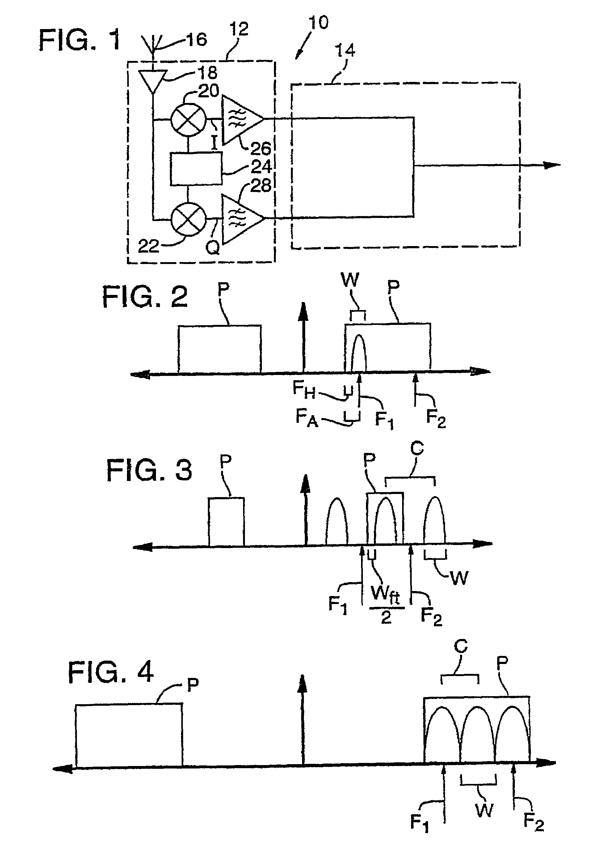
[0041]A significant aspect of the present invention is the basic division of functions between discrete-time (digital) and continuous-time (analog) components characteristic of the invention, which is described with reference to FIG. 1.

[0042]In FIG. 1, analog portion 12 of a device 10 according to the present invention receives an incoming signal from a preferably removable / exchangeable antenna 16. A suitable broad-band or tunable RF amplifier 18 then amplifies the signal. Alternatively, the invention could also be used to tune an intermediate frequency from previous analog processing, rather than an incoming signal directly from antenna 16 and amplifier 18.

[0043]The signal is then split into two signal paths and fed to first and second mixers 20, 22. The first and second mixers 20, 22 are supplied with a quadrature local oscillator signal from a preferably coarse-stepped local oscillator 24. The mixing operation translates to a near-baseband passband an upper high frequency spectru...


PUM


Abstract

A disclosed method tunes a signal from a channelized spectrum having a predetermined channel spacing. A signal of interest having a predetermined maximum bandwidth is mixed with a local oscillator signal, which has a frequency that is an integer multiple of the channel spacing or one-half of a channel spacing displaced from an integer multiple of the channel spacing. The local oscillator signal is selected to frequency translate the signal of interest to within a near-baseband passband whose lower edge is spaced from DC by at least about the maximum bandwidth of the signal of interest. Problems associated with 1 / f noise, DC offsets, and self-mixing products are avoided or substantially diminished. Other methods and systems are also disclosed.

Description

CROSS-REFERENCE TO RELATED APPLICATIONS[0001]This application is a continuation of U.S. patent application Ser. No. 10 / 032,526 filed Oct. 27, 2001, now U.S. Pat. No. 6,631,256, which is a continuation of U.S. patent application Ser. No. 09 / 317,781 filed May 24, 1999, now U.S. Pat. No. 6,427,068, which is a divisional of U.S. patent application Ser. No. 08 / 713,761 filed Sep. 13, 1996, now U.S. Pat. No. 5,937,341.FIELD OF THE INVENTION[0002]This invention relates generally to devices and methods for receiving and transmitting RF signals. More particularly, this invention relates to an especially useful device and method for receiving and tuning RF signals, with quadrature mixing to a near baseband passband performed in continuous-time and image rejection and translation to baseband performed in discrete-time. The device may also be adapted to transmit RF signals if desired.BACKGROUND OF THE INVENTION[0003]Standard RF receiver design incorporates conversion of incoming high frequency s...

Claims


Application Information

Patent Timeline
Patent Type & Authority Patents(United States)
IPC IPC(8): H04B1/10H03D3/00H03D7/16H04B1/26H04B1/30
CPCH03D3/007H03D3/009H03D7/165H04L25/067H04B1/06H04B1/10H04B1/16H04B1/30H04B1/26
Inventor SUOMINEN, EDWIN A.
Owner WASHINGTON RES FOUND
Why Eureka
Try Eureka