Apparatus and Method for Plasma Ignition with a Self-Resonating Device

a self-resonating device and apparatus technology, applied in the direction of plasma technique, electrical apparatus, electric discharge tubes, etc., can solve the problems of deteriorating the reactor, requiring the use of high voltage drive coils, affecting the efficiency of inductively coupled plasmas, etc., and achieve the effect of reducing the frequency of replacing parts

Active Publication Date: 2017-10-19
MKS INSTR INC
View PDF17 Cites 210 Cited by
  • Summary
  • Abstract
  • Description
  • Claims
  • Application Information

AI Technical Summary

Benefits of technology

The invention has advantages such as reducing the need for high voltage to cause plasma ignition, reducing the frequency of part replacement due to exposure to high voltages, arcs, and punch through, reducing costs due to eliminating the necessity of expensive parts and custom ignition designs, allowing for a wider range of chamber materials and coatings due to the elimination of high voltage requirements, and enabling high-rate pulsed plasma processing due to the ability to ignite with the process gas and avoid switching from an inert gas mixture. Other advantages include a reduction in tuning range requirement for inductively coupled plasma, simplified electronics due to the use of a self-resonating device, and elimination of an otherwise needed ignition switching scheme.

Problems solved by technology

However, some RF inductively coupled plasmas are not purely inductive because the drive currents are only weakly coupled to the plasma.
Consequently, RF inductively coupled plasmas are often inefficient and require the use of high voltages on the drive coils.
The ion bombardment deteriorates the reactor and can contaminate the process chamber and the material being processed.
The ion bombardment can also cause damage to the material being processed.
Microwave and inductively coupled plasma sources can require expensive and complex power delivery systems.
Application of a high voltage to ignite a plasma can cause several difficulties, for example, arcing outside of the ignition window (e.g., the standard operating ranges for pressure, gas flow, and / or gas species for successful ignition) and / or electrical breakdown of dielectrics (e.g., punch through).
Additional undesired arcing and electrical breakdown of dielectrics can cause damage to the plasma chamber and / or system parts.
Damaged parts can require frequent replacement and can be expensive.
Another difficulty of applying a high voltage to ignite is that typically a custom ignition design is needed for different types / shapes of plasma sources.
In addition to the difficulties described above, each of these ignition techniques has difficulties.
Spark plugs typically have a limited lifetime due to for example, relays used in the spark plug, thus requiring frequent replacement.
This can cause a limited lifetime for the electrodes and / or limited material options for the electrode.
Block ignition creates a potential for plasma arcing and can limit the choices for block materials / coatings.

Method used


Image

  • Apparatus and Method for Plasma Ignition with a Self-Resonating Device
  • Apparatus and Method for Plasma Ignition with a Self-Resonating Device
  • Apparatus and Method for Plasma Ignition with a Self-Resonating Device

Examples


Embodiment Construction

[0035]In general, one or more self-resonating devices are positioned relative to a plasma generation volume that is defined by a plasma chamber. During ignition, each self-resonating device creates its own plasma (e.g., ignition plasma) that at least partially ionizes a gas (e.g., ignition gas) that flows into the plasma generation volume. Energy is coupled into the plasma generation volume and a plasma (e.g., process plasma) ignites.

[0036]The partial ionization of the ignition gas allows for ignition of the process plasma to occur with less energy than is required to cause ignition of the process plasma without the partial ionization (e.g., without the one or more self-resonating devices.)

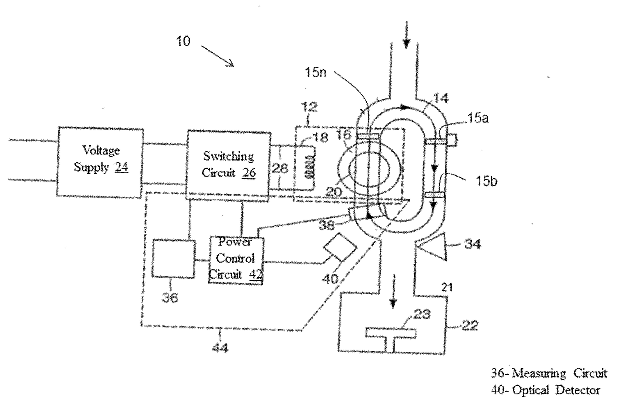
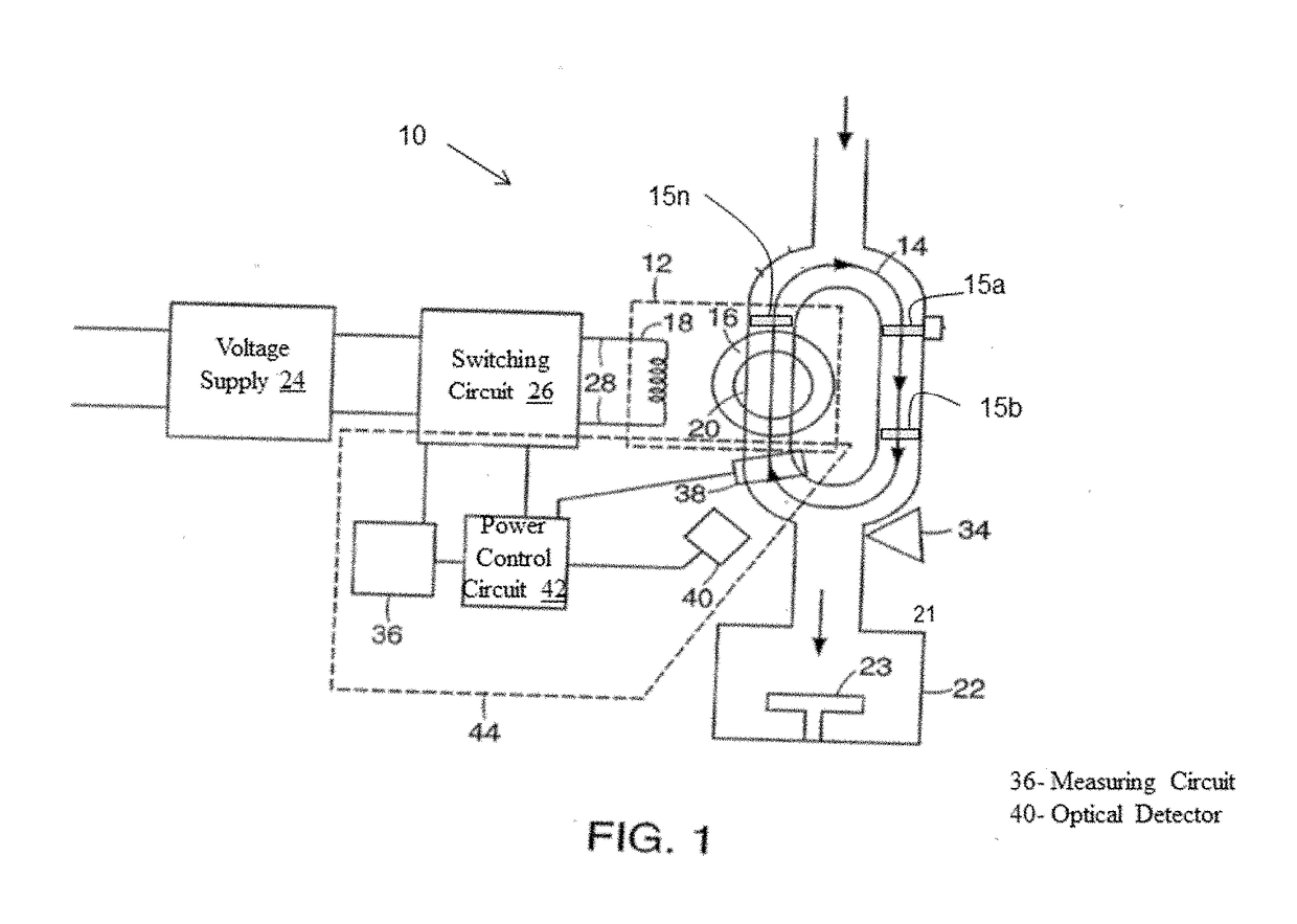
[0037]FIG. 1 is a schematic representation of a plasma source 10 for producing activated gases, according to an illustrative embodiment of the invention. The plasma source 10 provides activated gases to a semiconductor process chamber 22. The plasma source 10 includes a power transformer, a plasma...


PUM


Abstract

Methods and apparatus for igniting a process plasma within a plasma chamber are provided. One or more self-resonating devices are positioned within a plasma chamber relative to a plasma generation volume within the plasma chamber. The plasma generation volume is defined by the plasma chamber. Each of the self-resonating devices generates an ignition plasma. The ignition plasmas cause a partial ionization of an ignition gas. The partially ionized ignition gas allows for ignition of a process plasma by applying an electric field to the plasma generation volume.

Description

CROSS REFERENCE TO RELATED APPLICATION[0001]This application is a continuation of U.S. Ser. No. 14 / 616,089, filed Feb. 6, 2015, which is owned by the assignee of the instant application and is incorporated herein by reference in its entirety.FIELD OF THE INVENTION[0002]This invention relates generally to the field of igniting and sustaining plasma to generate activated gas containing ions, free radicals, atoms, and molecules. In particular, self-resonating devices partially ionize a process plasma ignition gas and are positioned relative to a plasma generation volume to cause a plasma ignition gas to ignite in the presence of an electric field.BACKGROUND OF THE INVENTION[0003]Plasma discharges can be used to excite gases to produce activated gases containing ions, free radicals, atoms and molecules. Activated gases are used for numerous industrial and scientific applications including processing solid materials such as semiconductor wafers, powders, and other gases. The parameters o...

Claims


Application Information

Patent Timeline
Patent Type & Authority Applications(United States)
IPC IPC(8): H05H1/46H01J37/32
CPCH05H1/46H05H2001/4607H05H2001/4652H01J37/32082H01J37/32174H01J37/32192H01J37/32247H01J37/32311H05H1/461H05H1/4652
Inventor SMITH, SHAUN T.WALTHER, STEVEN R.WU, CHEN
Owner MKS INSTR INC
Why Eureka
Try Eureka