System and method for frequency tunable microwave phase shifting

A phase shift and frequency technology, applied in the field of microwave photonics, can solve the problems of microwave photon phase shift instability, large output microwave amplitude jitter, complex phase adjustment of the system, etc. The Effect of Small System Size

Active Publication Date: 2013-09-25
HUAZHONG UNIV OF SCI & TECH
View PDF2 Cites 38 Cited by
  • Summary
  • Abstract
  • Description
  • Claims
  • Application Information

AI Technical Summary

Problems solved by technology

Among them, the research on the microwave photon phase shift system based on optical true time delay technology appeared first, but its structure is generally composed of many delay units, and phase differences are generated between channels with different time delays, and phase-shifted microwaves are formed after the photodetector beats signal, but the adjustment of the system phase is relatively complicated
In the microwave photon phase shift system based on optical heterodyne mixing, random phase noise caused by environmental factors is easily introduced into the two interfering optical paths, resulting in instability of the microwave photon phase shift output
The microwave photonic phase shifter based on the vector sum mainly realizes the phase shift of the microwave signal after the vector synthesis by changing the amplitude of two microwave signals of the same frequency, but there are shortcomings such as a small controllable phase shift range and a large output microwave amplitude jitter.
[0004] Obviously, the existing traditional microwave phase shifting methods above all have deficiencies, and how to generate high-quality photonics with small amplitude fluctuation and continuously adjustable phase in a large frequency range in the application of more and more microwave photonics systems It will be a big challenge to output a stable microwave electrical signal

Method used


Image

  • System and method for frequency tunable microwave phase shifting
  • System and method for frequency tunable microwave phase shifting
  • System and method for frequency tunable microwave phase shifting

Examples


Embodiment Construction

[0030] In order to make the object, technical solution and advantages of the present invention clearer, the present invention will be further described in detail below in conjunction with the accompanying drawings and embodiments. It should be understood that the specific embodiments described here are only used to explain the present invention, not to limit the present invention.

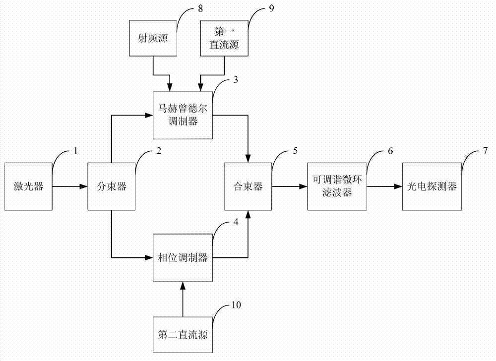
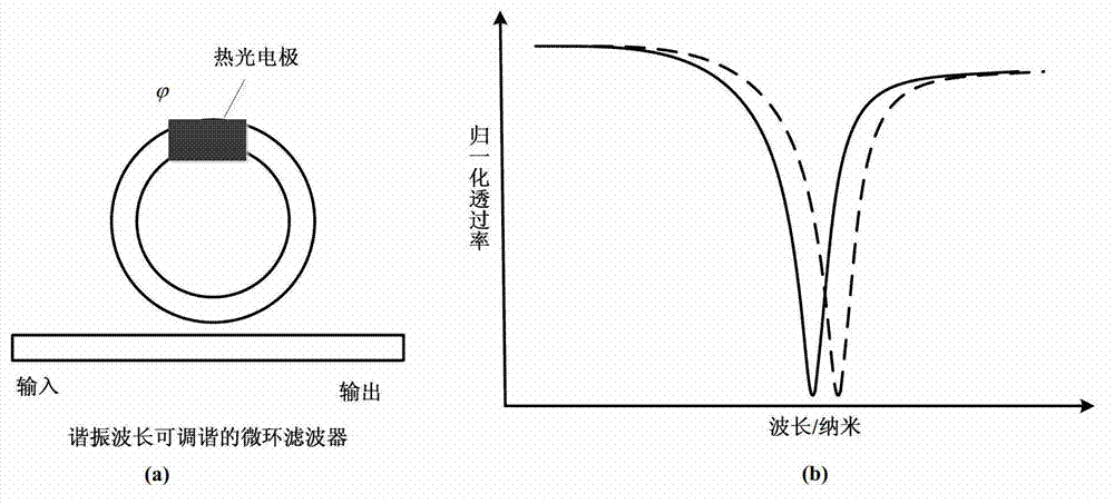
[0031] The invention relates to the preparation technology of optoelectronic devices in the field of microwave photonics, and provides an integrated dual parallel modulator (parallel Mach-Zehnder modulator (MZM) and phase modulator (PM)) and a resonant wavelength tunable microring The frequency-tunable microwave photon phase-shift system of the structure is mainly used to generate high-frequency microwave electrical signals with adjustable frequency and phase; it has the advantages of stable transmission performance, small fluctuation of output phase-shifted microwave amplitude, and continuously adj...


PUM


Abstract

The invention belongs to the field of microwave photonics, and discloses a system and method for frequency tunable microwave phase shifting. The method comprises the following steps that after a continuous light carrier is splitted, one beam of the continuous light carrier is processed by a MZ Mach-zehnder, and double-sideband optical signals restrained by the carrier are produced; the other beam of the continuous light carrier is processed by a phase modulator, and phase-shifted light carrier signals are produced; two beams of light signals are combined in a wave mode, one one-step sideband is removed through a tunable micro-ring filter in a filtering mode, a frequency-moved carrier signal and a phase-shifted carrier signal are obtained, photovoltaic conversion is carried out through a photoelectric detector, and a phase shift microwave electrical signal is produced; the resonant frequency of the tunable micro-ring filter is equal to any one-step sideband of the two one-step sidebands output by the MZ Mach-zehnder by changing the frequency of an input voltage drive signal and the resonant wavelength of the tunable micro-ring filter, and the frequency of the phase shift microwave signal is changed. The system and method for the frequency tunable microwave phase shifting is stable in output performance, fast in phase shift adjusting response, small in output microwave range fluctuation and continuously adjustable in wide frequency range.

Description

technical field [0001] The invention belongs to the field of microwave photonics, and more specifically relates to a frequency tunable microwave phase shift system and method based on a dual parallel modulator and a tunable microring filter structure. Background technique [0002] As a key device in microwave signal phase processing, microwave phase shifting system is mainly used in microwave photonics signal processing and optically controlled phased array radar system, and has important applications in satellite communication, mobile communication, military, aerospace and many other fields . The traditional microwave phase shifting system is mainly an electronic phase shifter, which is limited by the electronic bottleneck. The microwave signal generated has a small bandwidth, weak anti-interference ability, and a small phase shift range, which can no longer meet the urgent needs of high-performance radar. [0003] In recent years, there are three main realization principl...

Claims


Application Information

Patent Timeline
Patent Type & Authority Applications(China)
IPC IPC(8): H04B10/548H04B10/70
Inventor 付松年冯振华柯昌剑唐明刘德明
Owner HUAZHONG UNIV OF SCI & TECH
Why Eureka
Try Eureka