End-to-End (E2E) Tunnel Based on Shortest Point-to-Point (P2P) Path Computation

a tunnel and path computation technology, applied in the direction of data switching by path configuration, digital transmission, data switching network, etc., can solve the problems of complex path computation, multi-domain, multi-region, multi-layer network,

Active Publication Date: 2017-06-08
FUTUREWEI TECH INC
View PDF10 Cites 14 Cited by
  • Summary
  • Abstract
  • Description
  • Claims
  • Application Information

AI Technical Summary

Benefits of technology

[0005]In an embodiment, the disclosure includes a parent controller including a receiver configured to receive a request to compute a shortest end-to-end (E2E) path from a source to a destination through one or more network domains managed by one or more child controllers, and receive path segments and path segment costs computed by the child controllers in response to a request for the path segments and the path segment costs sent by the parent controller to the child controllers, wherein the path segments identify at least one of in-edge nodes, out-edge nodes, and inter-domain links corresponding to the network domains; a processor coupled to the receiver and configured to generate a candidate list using the path segments and the path segment costs received from the child controllers, construct a shortest path tree (SPT) from the source to the destination through the network domains by repeatedly removing one of the out-edge nodes corresponding to the path segment in the candidate list having a lowest cost and adding the one of the out-edge nodes to the SPT until the destination is reached, and determine the shortest E2E path based on the SPT; and a transmitter coupled to the processor and configured to transmit tunnel creation messages to the child controllers to create a tunnel along the shortest E2E path.

Problems solved by technology

However, path computation in large, multi-domain, multi-region, and / or multi-layer networks is complex and computationally intensive.

Method used


Image

  • End-to-End (E2E) Tunnel Based on Shortest Point-to-Point (P2P) Path Computation
  • End-to-End (E2E) Tunnel Based on Shortest Point-to-Point (P2P) Path Computation
  • End-to-End (E2E) Tunnel Based on Shortest Point-to-Point (P2P) Path Computation

Examples


Embodiment Construction

[0028]It should be understood at the outset that, although illustrative implementations of one or more embodiments are provided below, the disclosed systems and / or methods may be implemented using any number of techniques, whether currently known or in existence. The disclosure should in no way be limited to the illustrative implementations, drawings, and techniques illustrated below, including the exemplary designs and implementations illustrated and described herein, but may be modified within the scope of the appended claims along with their full scope of equivalents.

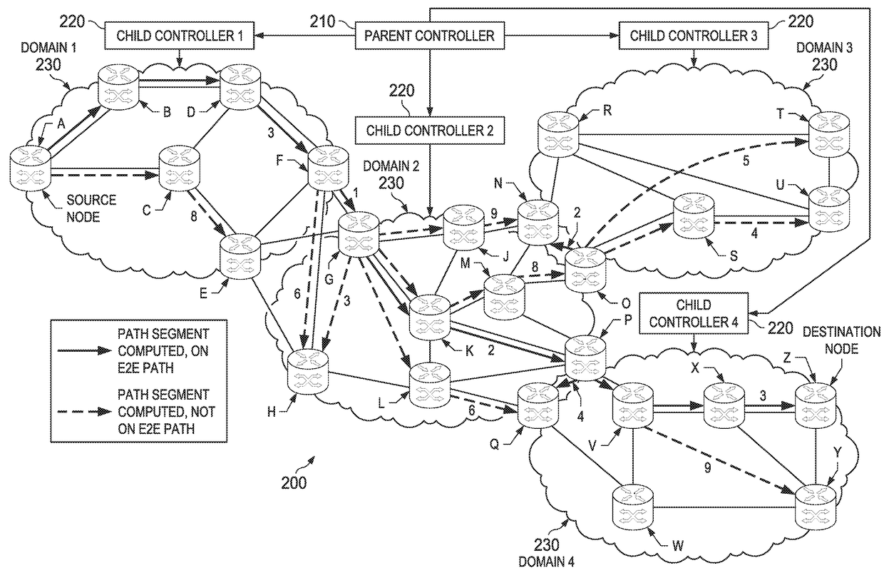
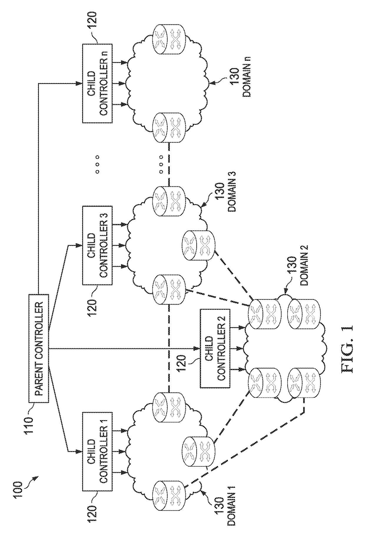
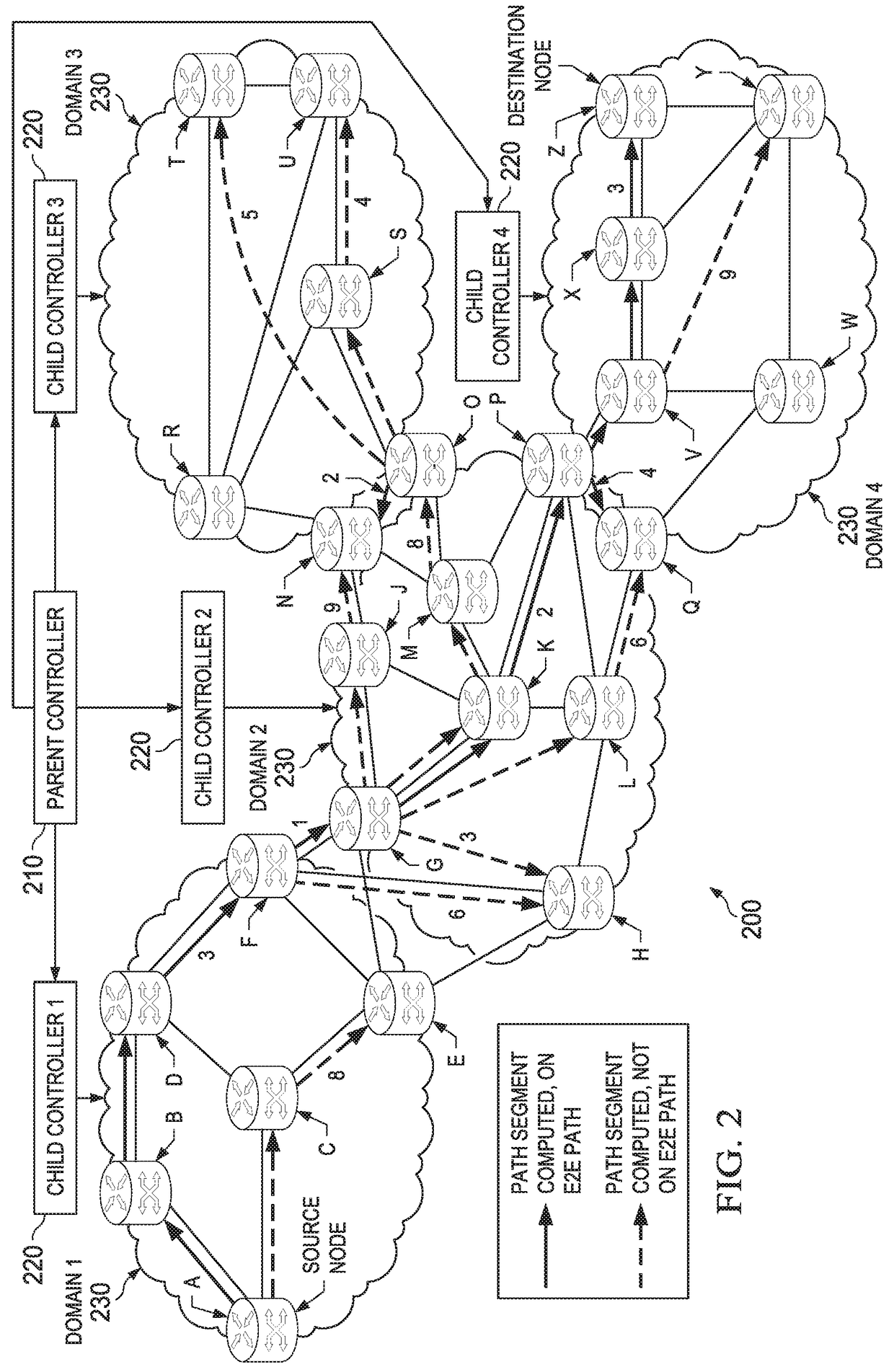
[0029]Telecommunication network providers may perform network management through a variety of approaches. One approach establishes E2E tunnels in hierarchical environments to provide reliable and secure data communication. However, this approach include drawbacks, such as complex system communication among its components (e.g., inaccuracies in network related information or summary), higher computation capability req...


PUM


Abstract

A method implemented in a parent controller including receiving a request to compute a shortest end-to-end (E2E) path from source to destination through network domains managed by child controllers, receiving path segments and costs computed by the child controllers, wherein the path segments identify in-edge nodes, out-edge nodes, and inter-domain links, generating a candidate list using the path segments and costs received from the child controllers, constructing a shortest path tree (SPT) from the source to the destination through the network domains by repeatedly removing one of the out-edge nodes corresponding to the path segment in the candidate list having a lowest cost and adding the one of the out-edge nodes to the SPT until the destination is reached, determining the shortest E2E path based on the SPT, and transmitting tunnel creation messages to the child controllers to create a tunnel along the shortest E2E path.

Description

CROSS-REFERENCE TO RELATED APPLICATIONS[0001]This application claims priority to U.S. provisional patent application No. 62 / 263,925 filed Dec. 7, 2015 by Huaimo Chen and titled “System and Method for Creating End-to-End Tunnel,” which is incorporated by reference.STATEMENT REGARDING FEDERALLY SPONSORED RESEARCH OR DEVELOPMENT[0002]Not applicable.REFERENCE TO A MICROFICHE APPENDIX[0003]Not applicable.BACKGROUND[0004]Telecommunications networks connect hosts to allow data communication between various geographically distant locations. Path computation for creating an E2E tunnel between hosts may be performed by a parent controller. The parent controller manages a number of child controllers through a hierarchical configuration. The child controllers implement the path computations received from the parent controller using network nodes within the domain or domains that the child controllers manage. However, path computation in large, multi-domain, multi-region, and / or multi-layer netw...

Claims


Application Information

Patent Timeline
Patent Type & Authority Applications(United States)
IPC IPC(8): H04L12/46H04L12/721
CPCH04L45/12H04L12/4633H04L45/124H04L45/04H04L45/48
Inventor CHEN, HUAIMO
Owner FUTUREWEI TECH INC
Why Eureka
Try Eureka