Clutch control device for 4-wheel drive vehicle

Active Publication Date: 2017-06-15
NISSAN MOTOR CO LTD
View PDF3 Cites 8 Cited by
  • Summary
  • Abstract
  • Description
  • Claims
  • Application Information

AI Technical Summary

Benefits of technology

[0009]In the clutch control device for a four-wheel drive vehicle of the present invention, the clutch control unit reduces the synchronization speed of the dog clutch more when engaging the dog clutch during deceleration than when the vehicle is not decelerating. The shock that is generated by engagement of the dog clutch during deceleration can thereby be reduced relative to when the vehicle is not decelerating, so that it becomes possible to achieve an improvement in the sound and vibration levels of the v

Problems solved by technology

When shock occurs at the time of engagement in this manner, there is the risk of adversely affecting vehicle behavior and the sound and vibration levels of the vehicle; in addition, the generation of such sound and vibration levels becomes significant upon deceleration as opposed to accelera

Method used


Image

  • Clutch control device for 4-wheel drive vehicle
  • Clutch control device for 4-wheel drive vehicle
  • Clutch control device for 4-wheel drive vehicle

Examples


Example

First Embodiment

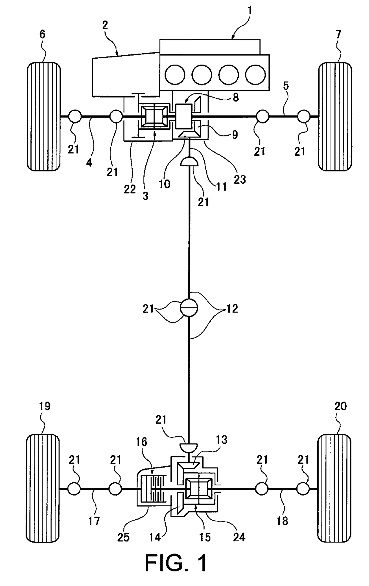
[0021]Referring initially to FIG. 1, a front wheel drive based four-wheel drive vehicle (one example of a four-wheel drive vehicle) is schematically illustrated with a clutch control device in accordance with a first embodiment.

Drive System Configuration of the Four-Wheel Drive Vehicle

[0022]FIG. 1 illustrates the configuration of the drive system of a front wheel drive based four-wheel drive vehicle to which is applied the clutch control device of the first embodiment. The drive system configuration of the four-wheel drive vehicle will be described below based on FIG. 1.

[0023]The front wheel drive system of the four-wheel drive vehicle is provided with a transverse engine 1 (drive source), a transmission 2, a front differential 3, a left front wheel drive shaft 4, a right front wheel drive shaft 5, a left front wheel 6 (main drive wheel), and a right front wheel 7 (main drive wheel), as illustrated in FIG. 1. That is, the drive force is transmitted from the transvers...

Example

Second Embodiment

[0080]The clutch control device of the second embodiment is an example in which the clutch control device is applied to a rear wheel drive based four-wheel drive vehicle, and the positional relationship of the dog clutch and the friction clutch that sandwich the differential is reversed from the positional relationship thereof in the first embodiment.

[0081]FIG. 10 illustrates the configuration of the drive system of a rear wheel drive based four-wheel drive vehicle to which is applied the clutch control device. The drive system configuration of the four-wheel drive vehicle will be described below based on FIG. 10.

[0082]The rear wheel drive system of the four-wheel drive vehicle is provided with a transverse engine 61 (drive source), a transmission 62, a rear propeller shaft 63, a rear differential 64, a left rear wheel drive shaft 65, a right rear wheel drive shaft 66, a left rear wheel 67 (main drive wheel), and a right rear wheel 68 (main drive wheel). That is, th...


PUM


Abstract

A clutch control device is provided for a 4-wheel drive vehicle. The clutch control device includes a 4WD control unit that controls the engagement and release of a friction clutch and a dog clutch which are arranged separately in the two paths. The 4WD control unit has a synchronization speed control unit, and at a time of transition from a disconnected, two-wheel drive mode, in which the friction clutch and the dog clutch are released, to a connected, four-wheel drive mode, in which the friction clutch and the dog clutch are engaged, the synchronization speed control unit reduces a synchronization speed of the dog clutch more during vehicle deceleration than when the vehicle is not decelerating.

Description

CROSS-REFERENCE TO RELATED APPLICATIONS[0001]This application is a U.S. National stage application of International Application No. PCT / JP2015 / 055246, filed Feb. 24, 2015, which claims priority to JP Patent Application No. 2014-038479 filed on Feb. 28, 2014, the contents of which are hereby incorporated herein by reference.BACKGROUND[0002]Field of the Invention[0003]The present invention generally relates to a clutch control device for a four-wheel drive vehicle in which a system for transmitting drive force to auxiliary drive wheels is provided with a dog clutch and a friction clutch.[0004]Background Information[0005]Conventionally, a front wheel drive based four-wheel drive vehicle in which a system for transmitting drive force to the rear wheels is provided with a dog clutch and a friction clutch is known (refer to, for example, Japanese Laid-Open Patent Application No. 2010-254058). In this four-wheel drive vehicle, when switching from a two-wheel drive mode to a four-wheel driv...

Claims


Application Information

Patent Timeline
IPC IPC(8): B60K23/08B60K17/34F16D23/02F16D13/00F16D21/00F16D48/06B60K17/02F16D11/00
CPCB60K23/08B60K17/02B60K17/34F16D11/00F16D13/00F16D2500/7061F16D48/06F16D23/02F16D2500/10431F16D2500/3108F16D2500/70424F16D21/00B60K17/3515B60K23/0808B60W10/16B60Y2400/424B60K17/344B60K17/35B60Y2400/421B60W10/119B60W10/12B60W2540/10B60W2510/1015B60W2510/0638B60W2540/18B60W2510/104B60W2520/105B60W2520/28B60W2520/10B60W2510/0604B60W40/101B60W30/02B60W10/04B60W10/02B60W40/114B60W30/045
Inventor OGAWA, KATSUYOSHIMORI, ATSUHIROMITSUISHI, SHUNICHIMORITA, MAKOTOTAKAISHI, TETSU
Owner NISSAN MOTOR CO LTD
Why Eureka
Try Eureka