Systems and methods for inspection using electromagnetic radiation

a technology of electromagnetic radiation and electromagnetic control, applied in the field of electromagnetic radiation inspection systems and devices, can solve the problems of lack of intuitive user experience and often built user interfaces for these viewing applications

Active Publication Date: 2017-06-15
INTEGRATED X INC
View PDF34 Cites 5 Cited by
  • Summary
  • Abstract
  • Description
  • Claims
  • Application Information

AI Technical Summary

Problems solved by technology

Furthermore, user interfaces for these viewing applications are often built without regard for human factors, and lack an intuitive user experience due to the sheer number of menus and buttons that will overwhelm an operator.

Method used


Image

  • Systems and methods for inspection using electromagnetic radiation
  • Systems and methods for inspection using electromagnetic radiation
  • Systems and methods for inspection using electromagnetic radiation

Examples


Embodiment Construction

[0022]The detailed description set forth below, in connection with the accompanying drawings, is intended as a description of various embodiments and is not intended to represent the only embodiments in which the disclosure may be practiced. The detailed description includes specific details for the purpose of providing a thorough understanding of the embodiments. In some instances, well-known structures and components are shown in simplified form for brevity of description.

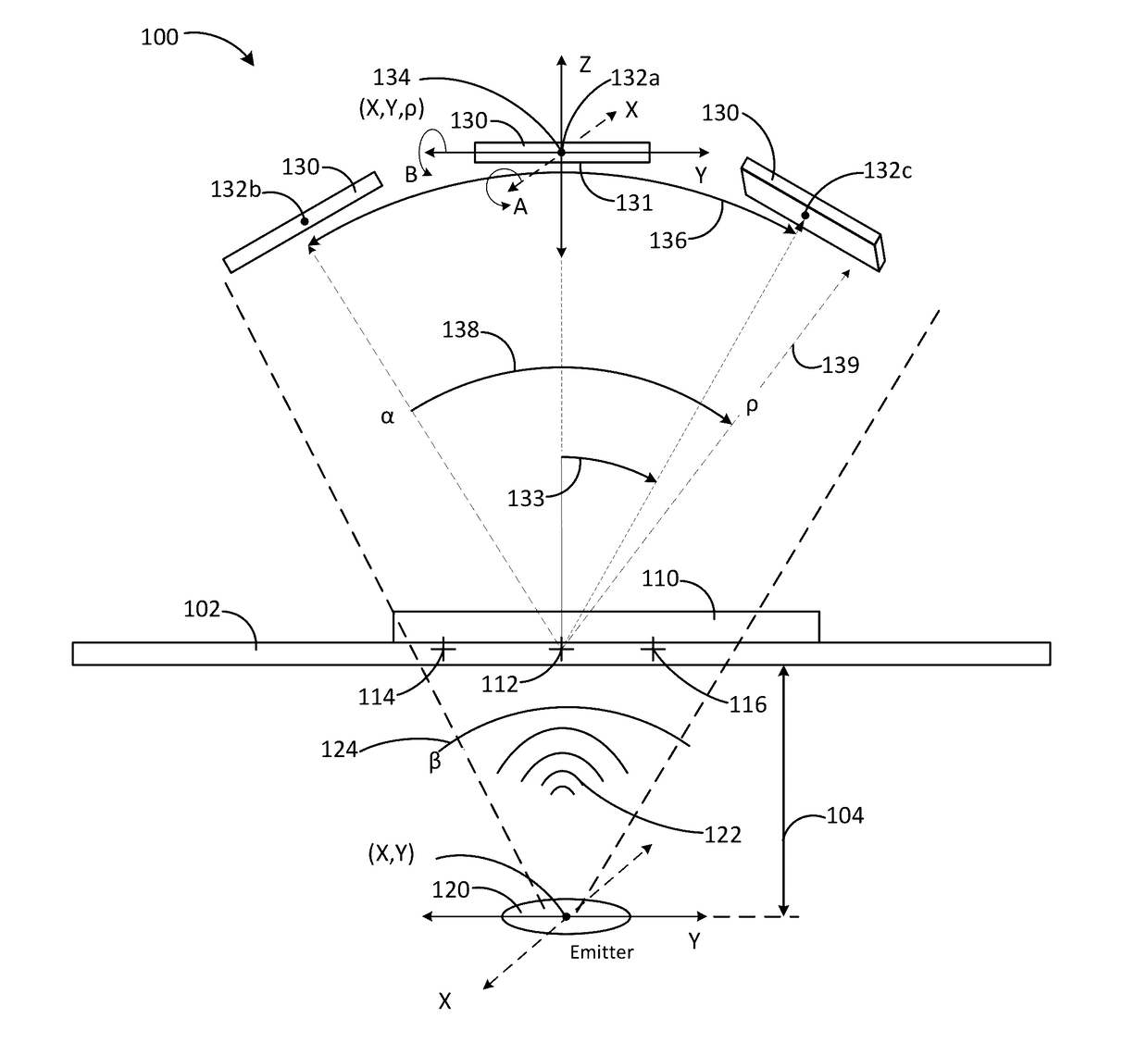
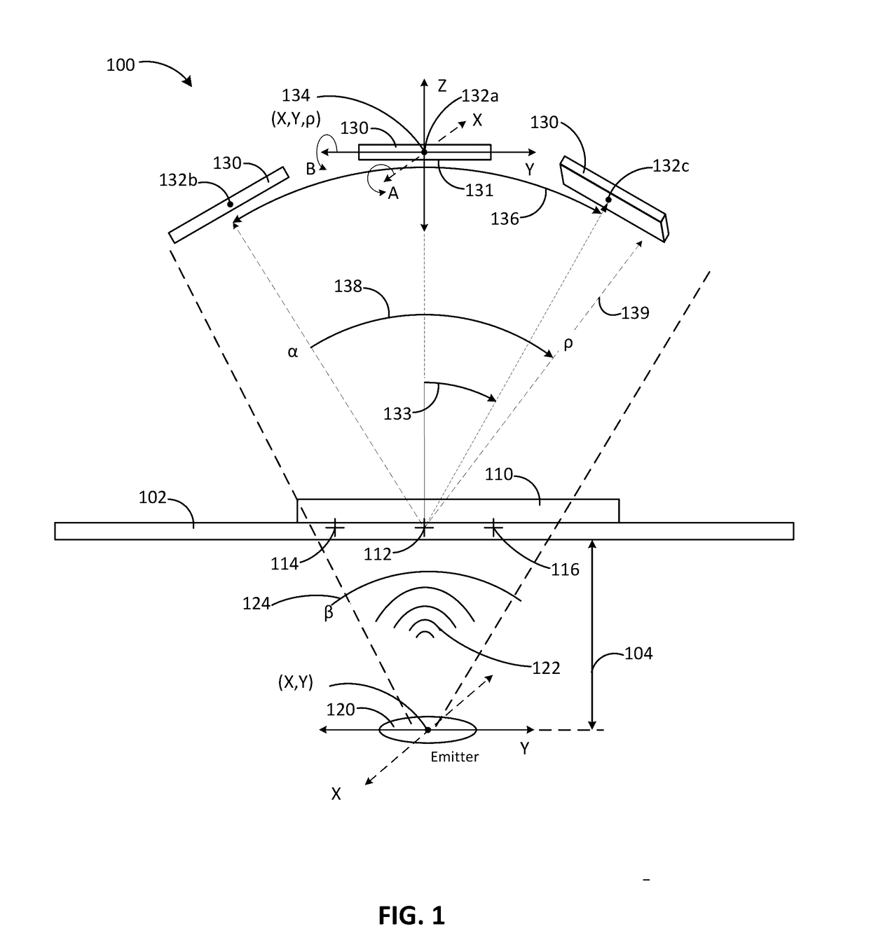
[0023]FIG. 1 is a graphical representation of a device for inspecting a component. The graphical representation is an elevation view of a device 100. The device 100 can have an inspection platform (platform) 102. The platform 102 can be a stationary, stable platform to support a component 110 to be inspected (e.g., inspected component). The component 110 can be a device or portion of a device that is to be inspected. In some embodiments, the component 110 can be a chipset, an integrated circuit, a printed circuit...


PUM

PropertyMeasurementUnit
distanceaaaaaaaaaa
aspect ratioaaaaaaaaaa

Abstract

This disclosure provides a system and method for inspecting a component. The device can have a detector positioning system coupled to a detector and operable to move the detector within five degrees of freedom. The device can have an emitter positioning system operably coupled to the emitter and operable to move the emitter in three dimensions. The device can move the detector to a reference point above the component, the reference point being separated by a radius (ρ) on the applicate axis from an inspection point on the component. The controller can also receive at least one input from a display, and command the detector to a detector position within a spherical dome centered on the reference point based on the at least one input.

Description

CROSS REFERENCE TO RELATED APPLICATIONS[0001]This application claims priority to U.S. Provisional Application, 62 / 265,004, filed Dec. 9, 2015, entitled “Systems and Methods for X-Ray Inspection,” the contents of which are hereby incorporated by reference in their entirety.BACKGROUND[0002]Technological Field[0003]This disclosure relates to electromagnetic (EM) inspection systems and devices. More specifically, this disclosure relates to motion control systems and methods for electromagnetic inspection devices.[0004]Related Art[0005]Some electromagnetic (e.g., x-ray) inspection systems use can implement various control devices, such as joysticks and switches, for motion control. In some examples, these input devices or control devices can control the movement of an x-ray emitter. The control devices can also control the platform upon which the component being inspected is placed.[0006]The system can provide visual feedback to the operator in the form of an x-ray image. Such an x-ray i...

Claims


Application Information

Patent Timeline
Patent Type & Authority Applications(United States)
IPC IPC(8): G01T7/00G01T1/29H04N5/32G01N23/04
CPCG01T7/00G01N23/04G01N2033/0093H04N5/32G01N33/00G01T1/2921G01N23/044
Inventor FUNG, HENRYSAHILU, BRUKMACAVEI, VALENTINLY, HUY
Owner INTEGRATED X INC
Why Eureka
Try Eureka