Protected membrane roof system

a membrane roof and membrane technology, applied in the field of roof systems and structures, can solve the problems of being susceptible to wind uplift or being blown off the roof, and significantly reducing the wind uplift resistan

Active Publication Date: 2017-06-22
FREEMAN THURMAN W
View PDF45 Cites 7 Cited by
  • Summary
  • Abstract
  • Description
  • Claims
  • Application Information

AI Technical Summary

Benefits of technology

The present invention provides some technical improvements for building and utilizing things that have specific benefits. These benefits are just one example of what this invention can offer.

Problems solved by technology

The technical problem addressed by this patent is how to improve the wind uplift resistance of a protected membrane roof system by securing a fastener assembly beneath the insulation board, which lies between the ballast material and the structure's deck.

Method used


Image

  • Protected membrane roof system
  • Protected membrane roof system
  • Protected membrane roof system

Examples


Embodiment Construction

[0049]The above described drawing figures illustrate aspects of the invention in at least one of its exemplary embodiments, which are further defined in detail in the following description.

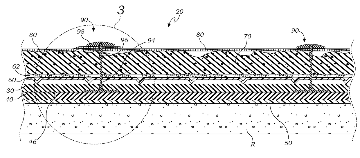
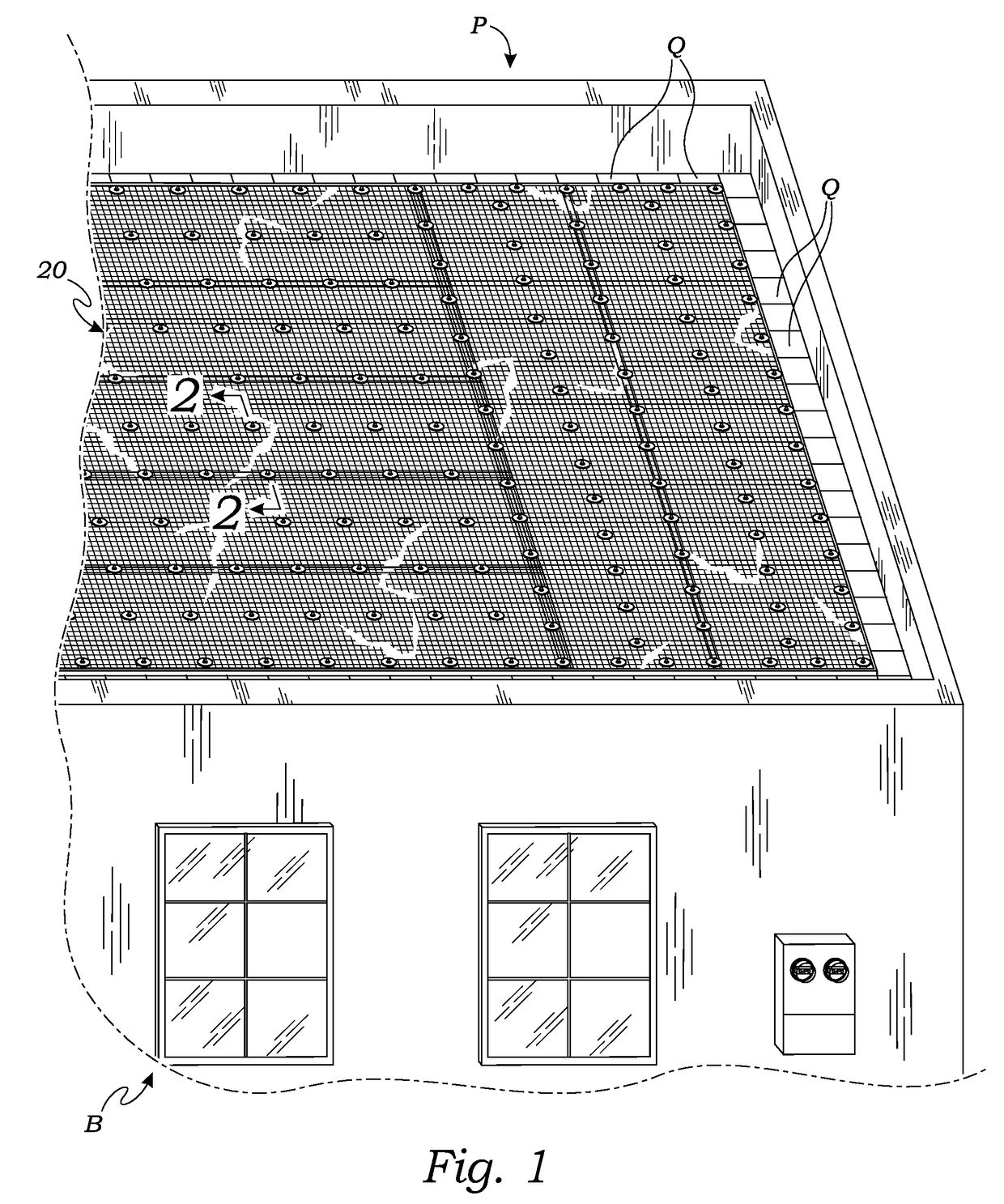
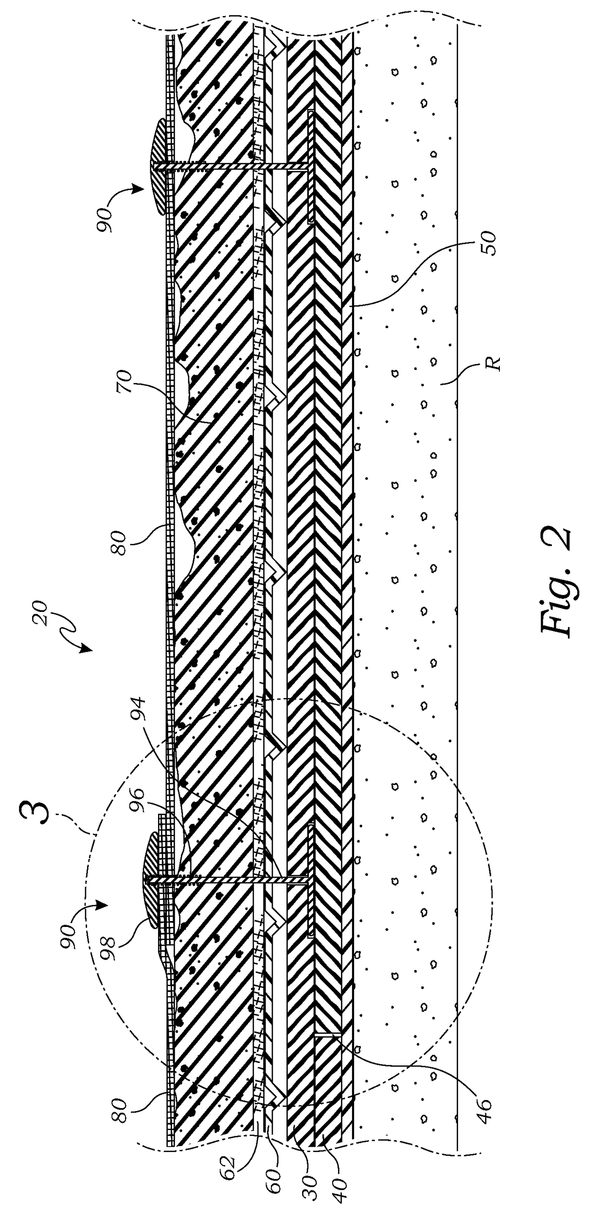
[0050]Turning now to FIG. 1, there is shown a “bird's eye” perspective view of an exemplary embodiment of a protected membrane roof system 20 according to aspects of the present invention. As known in the art, a protected membrane roof (“PMR”) is generally a typically flat roof having one or more layers of insulation installed over the waterproofing membrane for protection against UV radiation, thermal shock, the elements, and physical abuse, whereas conventional roofs have the waterproofing membrane installed over the insulation leaving the membrane exposed to the elements. In Protected Membrane Roofs, ballast material such as soil, stones, pavers, or the like is applied over the insulation layer(s) for further insulation and protection effects as well as wind uplift resistance for the underlying...


PUM


Abstract

A protected membrane roof system for installation on a roof decking comprising an upper insulation board having an upwardly-facing upper board top surface and an opposite downwardly-facing upper board bottom surface and at least one through-hole communicating therebetween, a ballast material positioned over the upper insulation board, and at least one fastener assembly having a base seated substantially adjacent the upper board bottom surface, a rod extending substantially vertically from the base of sufficient size so as to extend through the through-hole of the upper insulation board and the ballast material, and a cap engaged with the rod above the ballast material, whereby the wind uplift resistance of the protected membrane roof system is improved and scour of the ballast material is reduced by effectively anchoring the ballast material to the upper insulation board beneath the ballast material.

Description


Claims


Application Information

Patent Timeline
Owner FREEMAN THURMAN W
Why Eureka
Try Eureka