Confinement locking bar

Inactive Publication Date: 2017-06-29
LEPAGE SIMON +1
View PDF52 Cites 5 Cited by
  • Summary
  • Abstract
  • Description
  • Claims
  • Application Information

AI Technical Summary

Benefits of technology

[0005]To provide for a confinement locking bar which quickly secures a door

Problems solved by technology

With the recent epidemic of shooting rampage, school and other public buildings are at risk.
The problem with that is that some of that furnit

Method used


Image

  • Confinement locking bar
  • Confinement locking bar
  • Confinement locking bar

Examples


Example

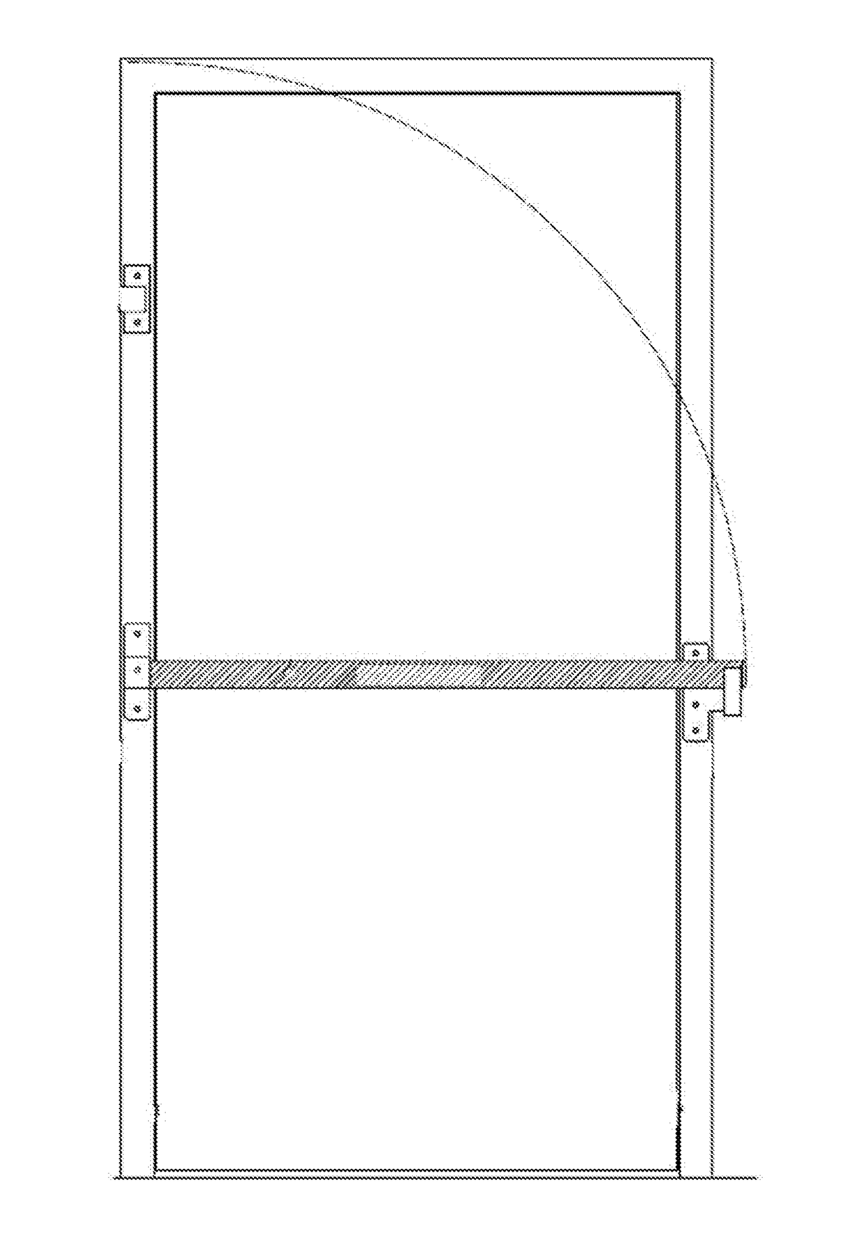
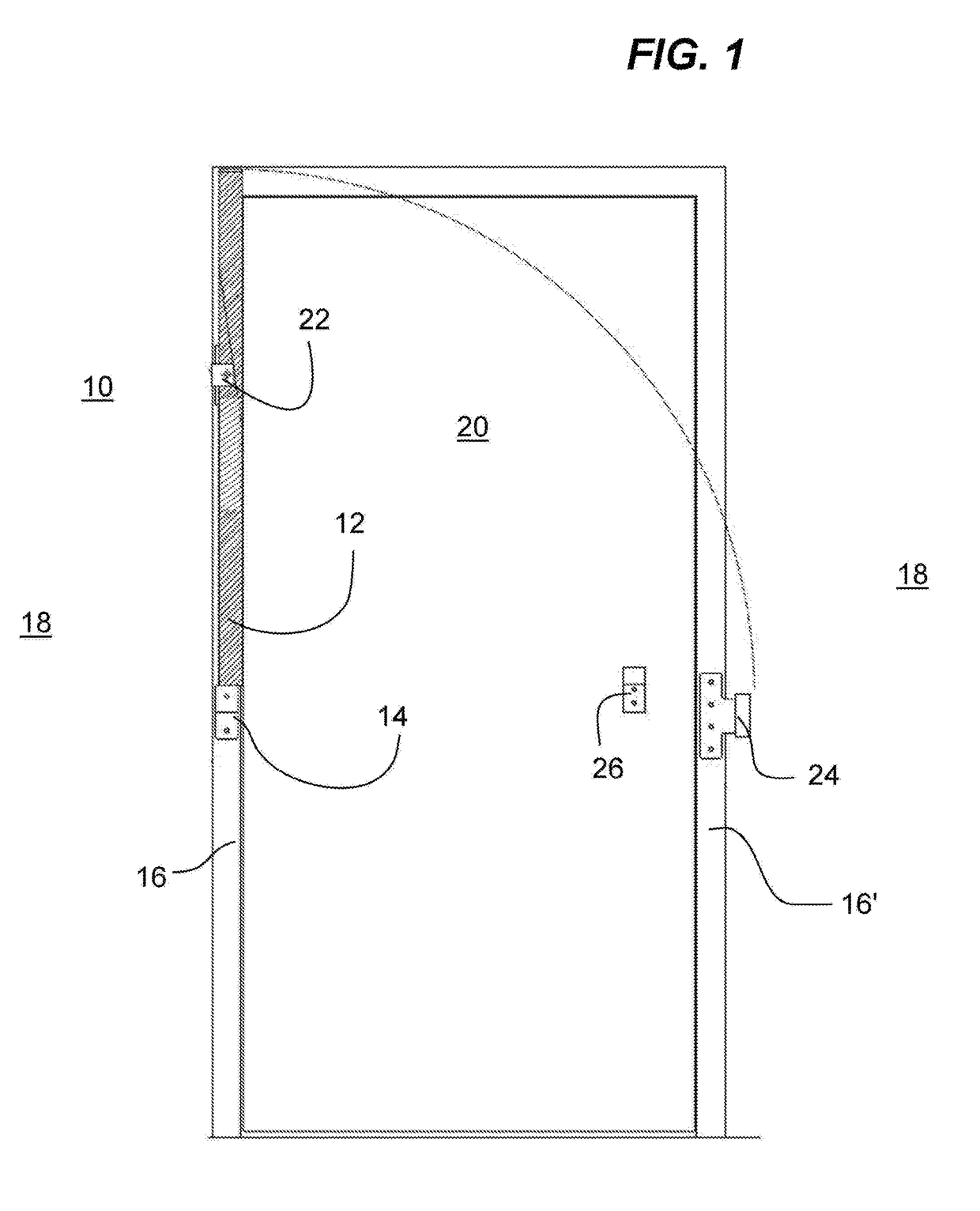
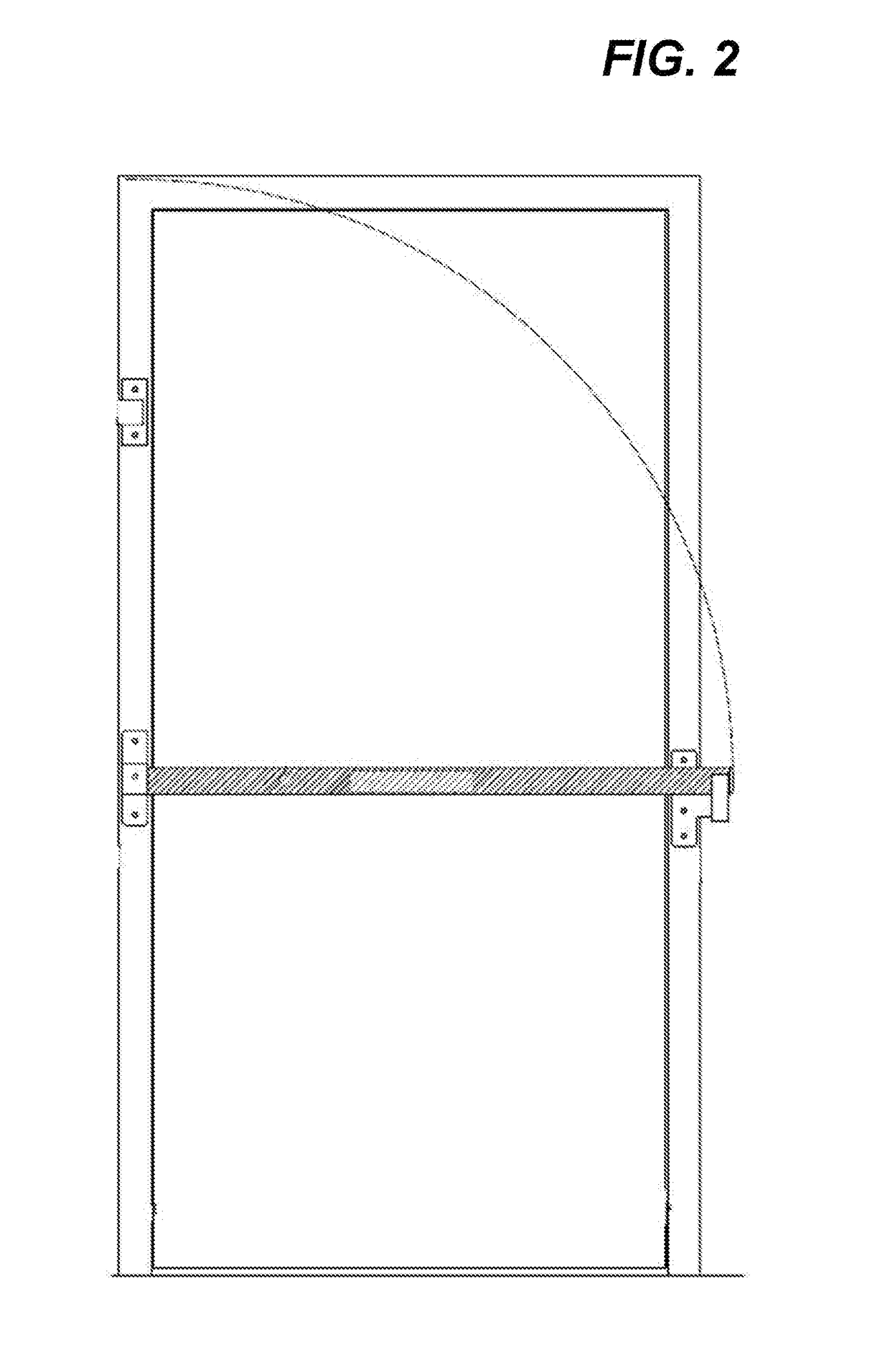
[0032]A confinement locking bar (10) is comprised of a bar member (12) made from a strong and resilient material and pivotally bolted at a pivot bracket member (14), the latter itself being fixedly attached to a door frame (16) or any other strong location on a wall section (18) proximal to a door (20) that needs to be secured.

[0033]The bar member (12), when not in use, is held in a vertical position, that is substantially parallel to the door (20), by way of a retainer member (22). The bar member (12) also has a latching member (24) that it can latch onto when it is lowered into its horizontal “confinement” mode. The latching member (24) is located on the opposite door frame (16′) or any other strong location on the wall section (18) proximal to the door (20) to be secured.

[0034]Additionally, since the door (20) is likely to be recessed in relation to both sides of the door frame (16, 16′), (a door is generally thinner than a wall) a blocker member (26) is conveniently located on t...


PUM


Abstract

A confinement locking bar is comprised of a bar made from a strong and resilient material and bolted at pivot bracket member to a door frame or any other strong location on a wall section proximal to a door to be secured. The bar is secured to a retainer member when it is in a vertical configuration. The bar has a latching member to latch on to when it is lowered into a horizontal “confinement” mode. The latching member is located on the opposite door frame. A blocker member is located on the door at a location where it is positioned in between the door and the bar when it is in confinement mode.

Description

FIELD OF THE INVENTION[0001]The present invention relates generally to building safety and security but more particularly to a confinement locking bar.BACKGROUND OF THE INVENTION[0002]Soon after the invention of the door came inventions related to securing that door. The earliest forms must have been to prop up a piece of wood with one end fitted in a notch carved in the floor and the opposite end squeeze against the door. There is also the horizontal bar that is run across the width of the door or even a double door and which is secured by a pair of brackets located on each side of the door. There is also a variation of the horizontal bar which is rotationally attached at one end on one side of the door so that when not in use it is vertical and when in use it rotates down into a bracket to the side of the door.[0003]With the recent epidemic of shooting rampage, school and other public buildings are at risk. Schools especially are victims of such acts of violence. Police and other ...

Claims


Application Information

Patent Timeline
IPC IPC(8): E05C19/00E05C19/12
CPCE05C19/12E05C19/003
Inventor LEPAGE, SIMONFISET, GUY
Owner LEPAGE SIMON
Why Eureka
Try Eureka