Golf gear fitting system, golf gear fitting method, golf gear fitting program, golf swing classification method, golf shaft fitting system, golf shaft fitting method, and golf shaft fitting program

Inactive Publication Date: 2018-10-11
MITSUBISHI CHEM CORP
View PDF4 Cites 1 Cited by
  • Summary
  • Abstract
  • Description
  • Claims
  • Application Information

AI Technical Summary

Benefits of technology

[0016]According to the present invention, suitable golf gear can be determined by a small number of test hits. Therefore, the present invention is also a preferable tool for a beginner with an unsta

Problems solved by technology

In 2008, a regulation on the repulsive force of a golf club head was put into effect by the Rules of Golf, making it difficult to optimize ball carry by the club head alone.
As an undesirable effect of such an increase, it is difficult for a player to select the most suitable golf gear, especially the most suitable shaft, at time of purchasing a golf club.
However, when such a technique is used, it is necessary for a player to test many golf clubs by actually hitting golf balls.
Therefore, the player can only make a better choice, but it is still hard to make the best choice.
Thus, when clubs and shafts with significantly different properties are simulated based on the data

Method used


Image

  • Golf gear fitting system, golf gear fitting method, golf gear fitting program, golf swing classification method, golf shaft fitting system, golf shaft fitting method, and golf shaft fitting program
  • Golf gear fitting system, golf gear fitting method, golf gear fitting program, golf swing classification method, golf shaft fitting system, golf shaft fitting method, and golf shaft fitting program
  • Golf gear fitting system, golf gear fitting method, golf gear fitting program, golf swing classification method, golf shaft fitting system, golf shaft fitting method, and golf shaft fitting program

Examples


Example

First Embodiment

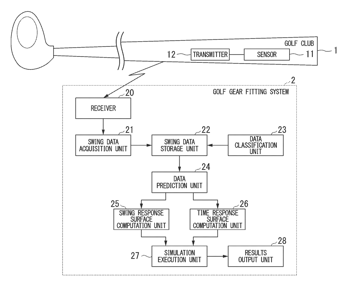
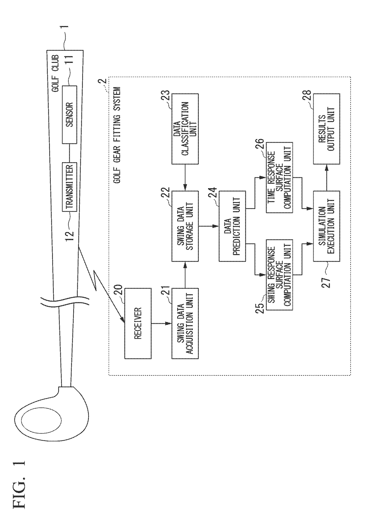
[0038]FIG. 1 is a block diagram showing a golf gear fitting system according to a first embodiment. In the diagram, golf club 1 is prepared in advance by installing a golf shaft with known specifications. Golf club 1 is equipped with sensor 11 and transmitter 12 inside the shaft at the grip portion. Transmitter 12 transmits the output from sensor 11 to the outside via wireless communication.

[0039]Sensor 11 may be installed outside of a shaft. For example, sensor 11 may be installed on the outer side of a shaft beneath the grip portion. By so setting, sensor 11 is installed on golf club 1 owned by a player. Alternatively, sensor 11 may also be installed inside a shaft of golf club 1 at the grip edge. By so setting, even more accurate swing data are obtained. Sensor 11 and transmitter 12 are preferred to be integrated. When sensor 11 and transmitter 12 are not integrated, it is preferred that transmitter 12 and the battery or the like built into the transmitter be set ...

Example

Second Embodiment

[0134]Next, a second embodiment is described by referring to FIG. 1. In the first embodiment, head behavior is computed through the process of swing data acquisition unit 21, swing data storage unit 22, data classification unit 23, data prediction unit 24, swing response surface computation unit 25, time response surface computation unit 26 and simulation execution unit 27. Simulation execution unit 27 is set to compute the head behavior from the posture of the head and the coordinates of its position by simply assuming that the shaft is rigid. In the first embodiment, a high-performance computer is required as simulation execution unit 27. Therefore, a computer to operate as simulation execution unit 27 is preferred to be set at a server or the like, separately from swing data acquisition unit 21.

[0135]By contrast, in the second embodiment, head behavior is computed without using simulation execution unit 27. More specifically, swing data acquisition unit 21 is set...


PUM


Abstract

A golf gear fitting system (2) includes a swing data acquisition unit (21) to acquire swing data from a sensor (11) installed in a golf club (1), a swing data storage unit (22) to store the swing data acquired by the swing data acquisition unit (21), a data classification unit (23) to classify the swing data stored in the swing data storage unit (22), and a data prediction unit (24) to predict swing data of specifications not measured by the sensor (11) by referring to the swing data classified in the data classification unit (23).

Description

TECHNICAL FIELD[0001]The present invention relates to a golf gear fitting system, a golf gear fitting method, a golf gear fitting program, a golf swing classification method, a golf shaft fitting system, a golf shaft fitting method, and a golf shaft fitting program.[0002]The present application is based upon and claims the benefit of priority to Japanese Application No. 2015-102548, filed May 20, 2015, the entire contents of which are incorporated herein by reference.BACKGROUND ART[0003]In 2008, a regulation on the repulsive force of a golf club head was put into effect by the Rules of Golf, making it difficult to optimize ball carry by the club head alone. In response to the regulation, manufacturers switched their focus to the shaft, aiming to increase ball carry by optimizing the bending of a shaft. Accordingly, variations in shafts increased as of 2012, and combinations of shafts and club heads thereby brought about a further increase in variations of golf clubs. As an undesirab...

Claims


Application Information

Patent Timeline
IPC IPC(8): A63B60/46A63B53/00
CPCA63B60/46A63B53/00A63B2220/833A63B2225/50A63B2220/44A63B2220/34A63B2220/36A63B2102/32A63B53/10A63B53/12A63B2220/16A63B2220/40A63B53/005A63B69/3605
Inventor SHIMONO, SATOSHISUKUKI, KATSUYUKI
Owner MITSUBISHI CHEM CORP
Why Eureka
Try Eureka