Mounting device for pressure sensor calibration

A technology of pressure sensor and installation device, which is applied in the direction of measuring device, force/torque/power measuring instrument calibration/test, instrument, etc. It can solve the problems of insufficient portability, inability to directly use calibration work, bulky volume, etc.

Inactive Publication Date: 2020-02-14
湖南绚丽新材料科技有限公司
View PDF8 Cites 2 Cited by
  • Summary
  • Abstract
  • Description
  • Claims
  • Application Information

AI Technical Summary

Problems solved by technology

[0003] At present, there are deficiencies in the force measurement of non-standard testing machines on the market, such as unstable calibration values, bulky volume, inconvenient carrying, and low applicability of equipment, resulting in a high probability of misjudgment
[0004] Chinese patent (publication number: CN209085837U) discloses a mounting device for pressure sensor calibration, including a base plate, a first mounting plate and a second mounting plate, and the first mounting plate and the second mounting plate are arranged alternately in sequence; The side of the first mounting plate is provided with a first through hole, the outer wall of the first through hole is provided with a first air intake pipe, and the outer wall of the first air intake pipe is p

Method used


Image

  • Mounting device for pressure sensor calibration
  • Mounting device for pressure sensor calibration
  • Mounting device for pressure sensor calibration

Examples


Embodiment 1

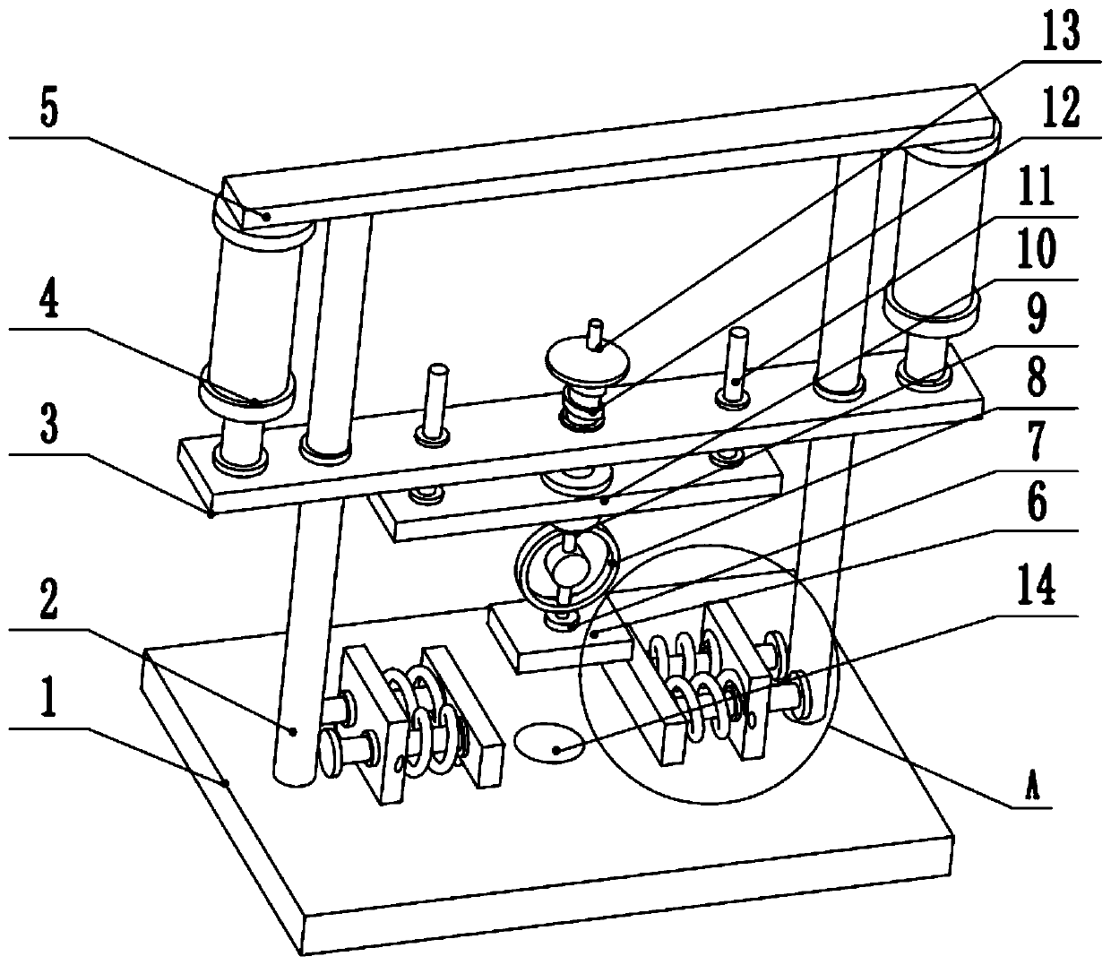
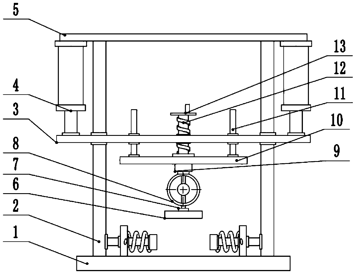
[0026] see Figure 1-3 , a mounting device for pressure sensor calibration, comprising a base plate 1, support columns 2 are provided at the left and right ends of the upper surface of the base plate 1, a top plate 5 is provided at the top of the support column 2, and a cylinder is provided at the left and right ends of the lower surface of the top plate 5 4. The piston rod of the cylinder 4 is fixedly connected to the lifting plate 3, the left and right sides of the lifting plate 3 are slidably connected to the support column 2, the middle part of the lifting plate 3 is slidably connected to the middle part of the first guide rod 11, and the lower end of the first guide rod 11 Fixedly connected to the fixed plate 10, the middle part of the upper surface of the fixed plate 10 rotates to connect the lower end of the screw mandrel 12, the upper end of the screw mandrel 12 is provided with a runner 13, the middle part of the screw mandrel 12 is threaded to connect the middle part ...

Embodiment 2

[0029] see figure 1 , the other content of this embodiment is the same as that of Embodiment 1, the difference is that: the middle part of the bottom plate 1 is provided with a relief groove 14 . For some electronic sensors, an external data line is required during use, so a relief slot 14 is provided in the middle of the bottom plate 1, so that the data line of the sensor can pass through the relief slot 14 and connect to related equipment, avoiding on the one hand In the process of applying pressure, the data line is crushed, on the other hand, it can make the whole device look more neat.

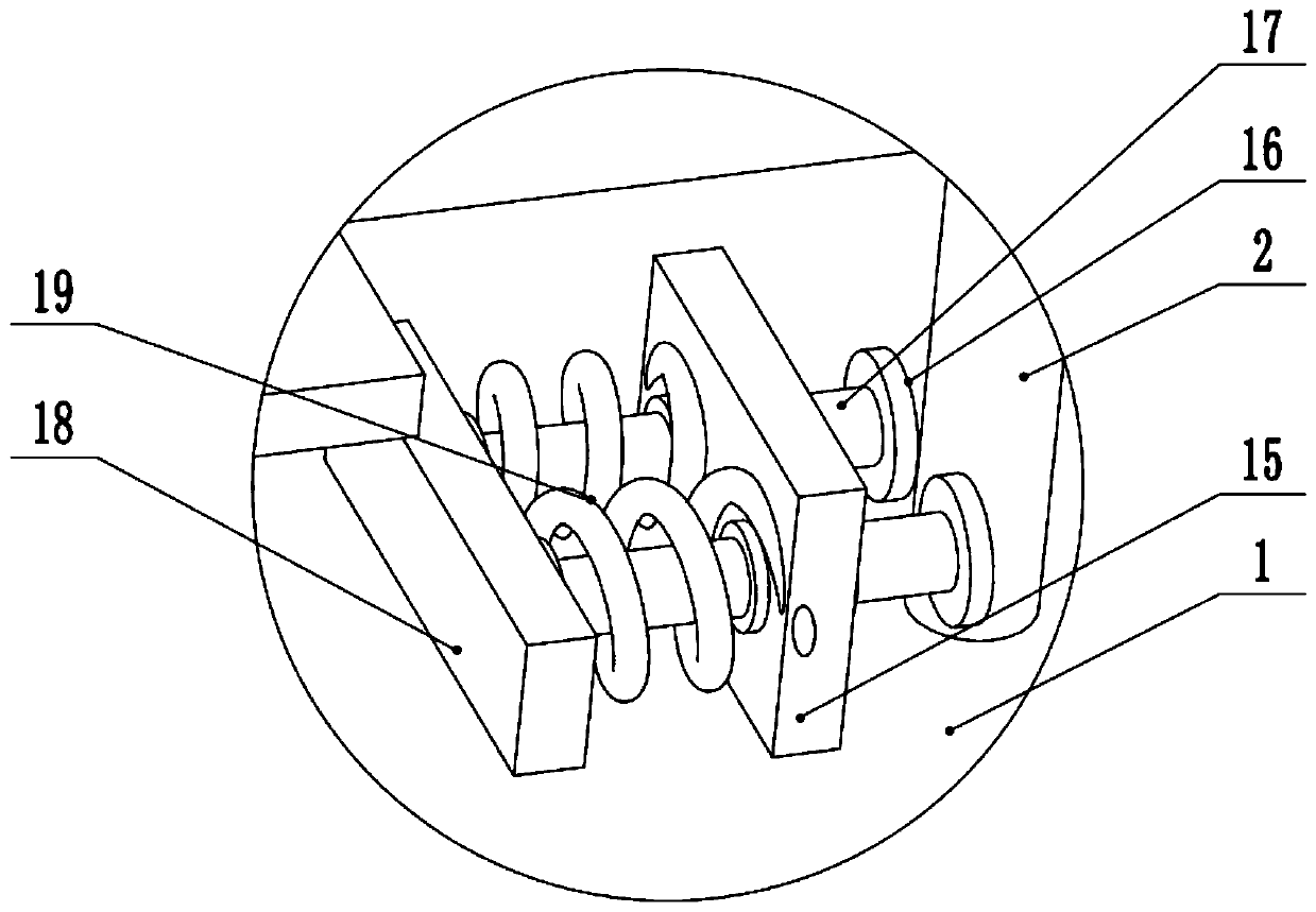
[0030] During the implementation of the present invention, first push the clamping plate 18 to both sides, place the sensor to be calibrated in the middle of the bottom plate 1, loosen the clamping plate 18, and under the action of the spring 19, the two clamping plates on both sides The clamping plate 18 slides toward the center of the device. At this time, the clamping plate 18 can fix...


PUM


Abstract

The invention, which relates to the technical field of sensor calibration, discloses a mounting device for pressure sensor calibration. The mounting device comprises a bottom plate. Supporting columnsare arranged at left and right ends of the upper surface of the bottom plate; a top plate is arranged at the tops of the supporting columns; cylinders are arranged at left and right ends of the lowersurface of the top plate; and a lifting plate is fixedly connected to piston rods of the cylinders. The middle part of the lifting plate is in sliding connection with middle parts of first guiding rods; the lower ends of the first guiding rods are fixedly connected with a fixing plate; and the middle of the upper surface of the fixing plate is in rotation connection with a lower end of a lead screw. A second connecting base is arranged in the middle of the lower surface of the fixing plate; the lower end of the second connecting base is connected with the upper end of a force measuring ring;the lower end of the force measuring ring is connected with a first connecting base; and the lower end of the first connecting base is fixedly connected with a pressing plate. According to the invention, the mounting device has advantages of simple structure and light weight and can move with a vehicle; calibration work can be directly carried out on a construction site conveniently; the convenience is improved; and the mounting device is suitable for application and popularization.

Description

technical field [0001] The invention relates to the technical field of sensor calibration, in particular to a pressure sensor calibration installation device. Background technique [0002] Due to the continuous development of the country's industry, various forms of non-standard force measuring instruments require on-site calibration. Among them, the load cell is an important part of the non-standard instrument measurement verification. Every measurement institution is faced with the calibration problems of various new instruments, and this method makes on-site calibration of tension and pressure sensors more convenient and quicker. According to the following requirements for fixtures of electronic universal testing machine, non-metallic material testing machine and non-standard standard force testing machine, the fixture is stable and reliable to ensure accurate force measurement. [0003] At present, there are deficiencies in the force measurement part of non-standard te...

Claims


Application Information

Patent Timeline
IPC IPC(8): G01L25/00
CPCG01L25/00
Inventor 易宏博杨姗
Owner 湖南绚丽新材料科技有限公司
Why Eureka
Try Eureka